Architect / Geometer / Historian
Monday, November 20, 2023
The Practical Geometry of the Parson Barnard House:
the Bents
This is the second part of my study of the use of geometry in the layout and design of the Parson Barnard House, in North Andover, Massachusetts.
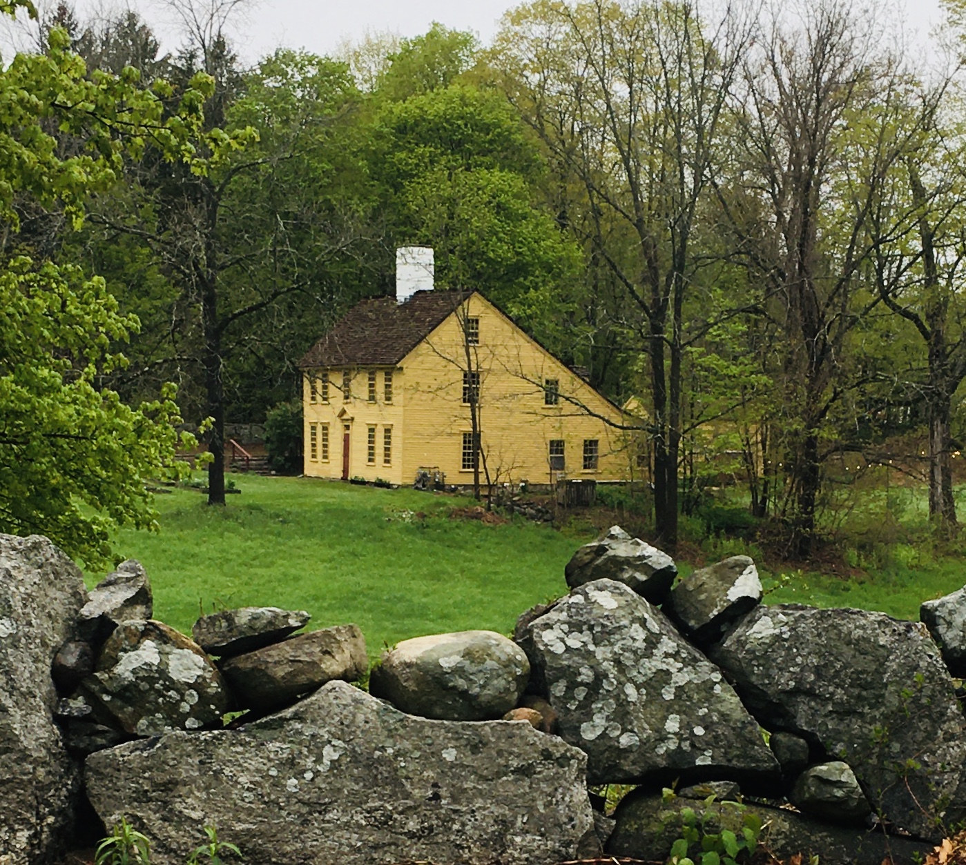
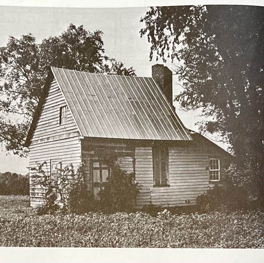
Here's the house. The left section, the 'front', was built in 1715; the saltbox added in 1720. The rear extension to the right came in the 1950's.
For my first post on the Parson Barnard House please see the link at the bottom of this page.*
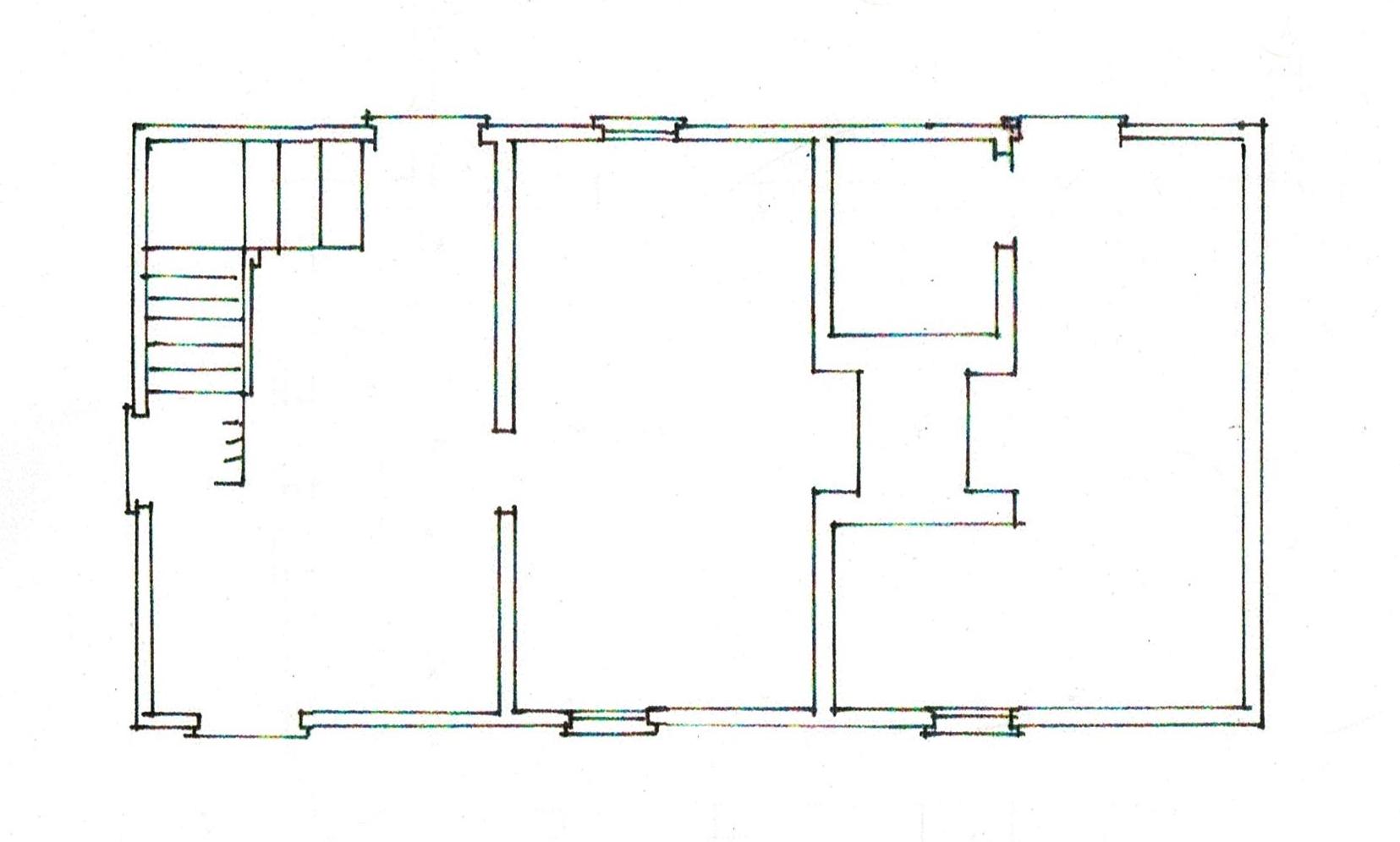
The first floor plan shows the 2 back wings. The middle section, labeled kitchen, back hall, and study is the 1720 saltbox addition. The laundry and entry spaces were added 230 years later.
The plan shows a step down into the saltbox addition.
The side elevation also shows this step down. The dashed lines locates the floors and the step down.
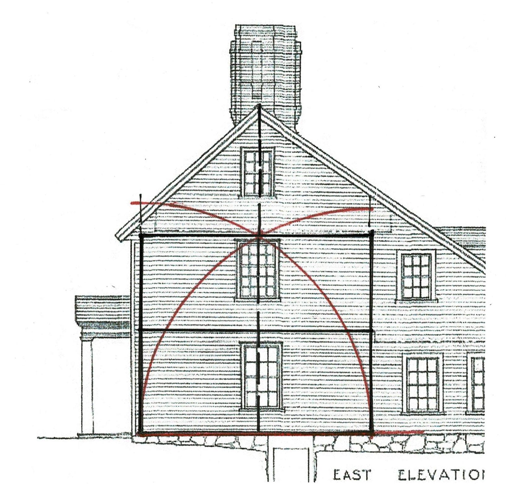
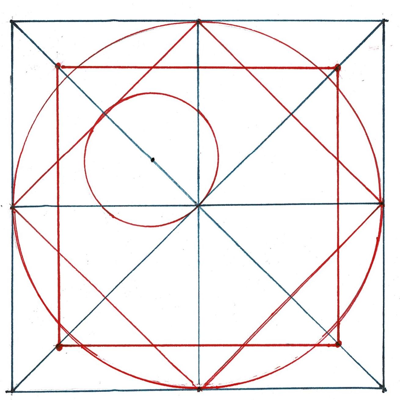
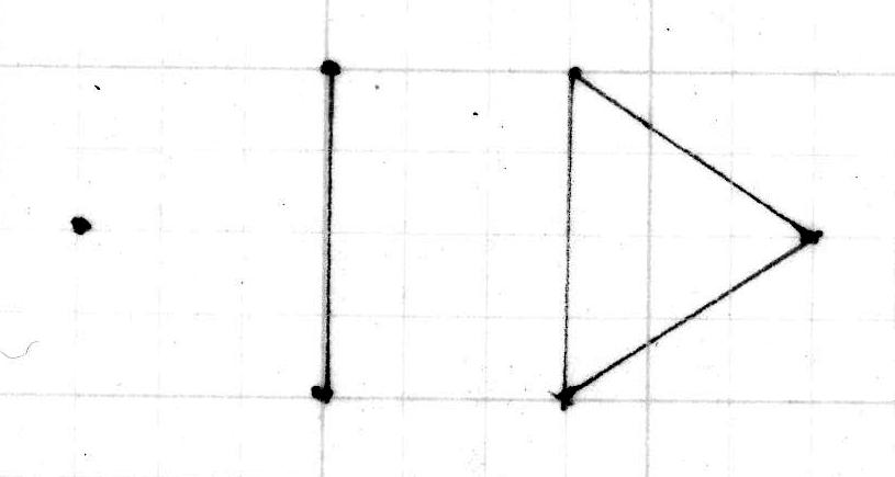
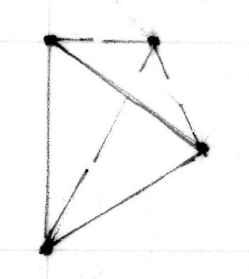
The layout Lines locate the inside edge of the posts and the inside width between the posts on either corner of the house. Together they outline 3 sides of a rectangle, the layout for the bents of the frame. The radii of the arcs is the width of the frame. They cross at the placement for the lower side of the beam which supports the attic floor joists. It is the upper beam of the bents that frame the house.
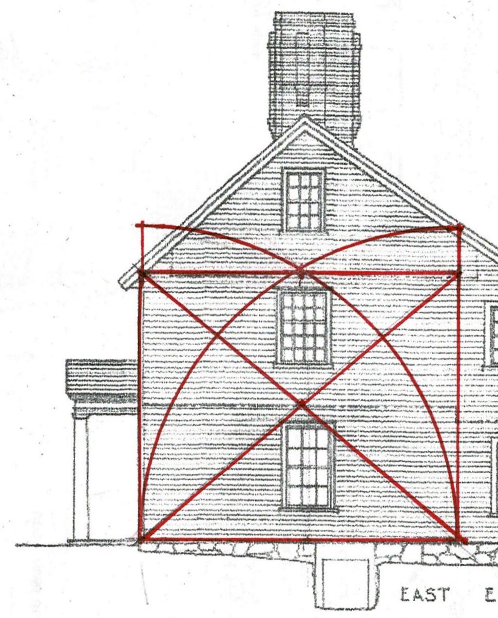
This use of geometry matches the way the parlor width was determined. The thin black Line marks the rectangle which is the inside of the bent.
The rectangle from that layout crossed with its diagonals. Where the Lines cross is the height of the beam which carries the second floor joists.
*See note below for more information.
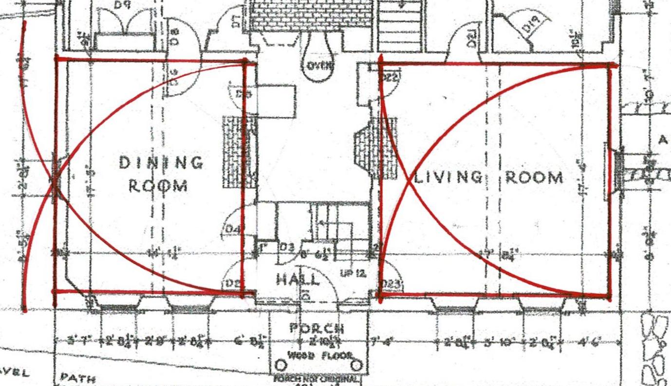
For reference here is the geometry of the first floor plan with the Hall on the right, a square; the Parlor on the left, a rectangle whose width is laid out by the arcs. This geometry is laid out from the inside edges of the posts.
When the same geometry is used to lay out the bent using the width from the outside of one post to the other as the dimension, the crossing of the arcs is at the upper side of the attic beam.
**Look back at the elevation of the house with the rectangle derived from the interior dimensions. Note that the second floor and attic windows - which appear to be original - are centered on the space. Using the outer dimensions the windows are no longer centered.
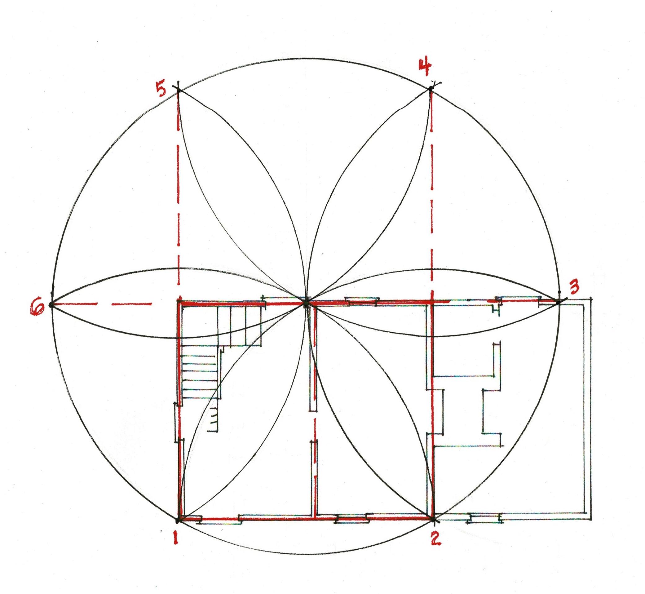
Here is the design for the 6 bents for the Parson Barnard House (without the braces). This simple layout requires only basic knowledge of Practical Geometry.
The bottom red line is the sill.
Do the layout differences I've shown here - between the use of the inside and the outside widths - provide evidence that the interior widths were used? Or do they simply mean the drawing is too small, my lines too thick or not perfectly placed, that the attic framing might yield other information for an accurate assessment?
*
The Practical Geometry of the Parson Barnard House
Tuesday, November 7, 2023
The Practical Geometry of the Parson Barnard House
The Parson Barnard House, North Andover, Massachusetts, built in 1715. This picture was taken in 2022.
The original house is the front (left) section: 2 rooms up and down, each with a fireplace. The chimney in the middle served all the fireplaces and acted as a radiator.
The saltbox extension was added c.1720. The rear wing dates to the 1950's.
John Abbott measured and drew the floor plans and elevations of the house for HABS in 1934. At that time it was thought that Simon Bradstreet had lived here.
Now we know the families of the Reverend Thomas Barnard and his son, the Reverend John Barnard, were the first residents from 1715 to 1757.
Here are the tools a Massachusetts Bay Colony carpenter had in 1715 for planning and laying out buildings*. He used a compass, a square, horizontal and vertical levels, a straight edge marked in regular increments (which might or might not be inches) and a line with a spool on one end and a plumb bob on the other. The builder also had an awl, chalk, charcoal, and an 8 or 10 ft. rod.

His square was small and might not have a true 90* corner. His inch, foot, rod, varied from those of other carpenters. He would have learned his skills as an apprentice to a master carpenter, become a journeyman, then a full-fledged carpenter. His training would have included practical geometry. Tape measures had not been invented, paper was precious. He drew plans on framing floors, on sheathing, on dirt. He did not need to be literate.
Using a compass, a straight edge and a scribe a carpenter could layout the plan on a board, then step off the plan on the site with his rod or his compass, set his lines, and true them. This is the same order in which we layout buildings today; we simply use more modern tools.
This is the floor plan of the original house.
Noted in black are the sills, the posts and beams for the first floor frame .
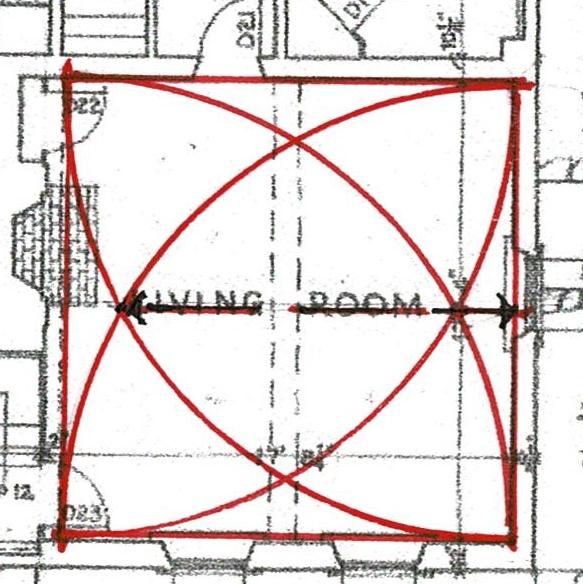
The carpenter knew the first floor would have a Hall - on the right labeled 'living room', and a Parlor - on the left called the 'dining room'.
Between them, in the center of the house would be the chimney stack with a separate flue for each of 4 fireplaces.
Here is the chimney above the roof with articulated flues.
These spaces add up to a house about 18 ft. wide by 42 ft. long.

The width and length of the house were stepped off with a compass or marked on a length of twine. The exterior of the house would have been staked. 3 foot units could have been stepped off 6 times for the width and 7 times for the length. Layout with a rod marked in feet would probably have been faster. A chalk line might have been snapped. Lines could have been tied to stakes for the men digging the foundation. Diagonals would have trued the foundation. All of this is similar to how we layout buildings today.
Stone foundations of pre-1900 houses tend to be vertical on the inside of the wall, the basement side, battened into the soil on the exterior. 2 lines would be required to accurately set the top of the foundation - where the sill would sit, where the outside wall of the house would stand.
The length of the beams of the frame, approximately 18 ft., probably determined the house width.
The Hall, the biggest room, was a multi- purpose room, used for cooking, chores, gathering. Often set in the southeast corner of the house, it had sunshine from early morning to late afternoon. Here the room is square with a beam to support the 2nd floor across its center. The arc of the 18' width locates the posts.

Note that the dimensions appear to begin at the inner side of the right hand posts, indicating that while the exterior of the foundation was laid 18 ft. x 42 ft., the layout for the timber frame appears to have been set from the sill and those first posts.
Laying out the geometry from the inside of the frame would have been a practical choice. The sills would not cover the line, but located beside it. Truing a rectangle by checking its diagonals to the outside corner of a post would be tricky, especially after the posts were in place. The framing timbers also needed to set to the line. And, the outside of a stone foundation could be irregular - as field stones are - without compromising the bearing of the frame on the foundation.
This length, this inside dimension, would also have been the one the framers used to lay out the mortise and tenon joints on the beams.
Next to the Hall is the chimney stack. In plan it is a 3/4/5 rectangle often used by masons to keep the bricks plumb and level during construction. The fireplaces fit within, their fires creating a massive heat sink.
The entry and staircase fit into the leftover space in front of the stack.
The Parlor, the room to the left, was used for business and formal occasions, to welcome and entertain visitors. Sometimes it was also the master bedroom.
It was smaller than the Hall and also had a centered beam. The arcs cross at the outside edge of the wall, setting the width of the room.
The length of that width could easily be measured from the layout of the Hall. Here the arcs cross, giving 2 points for drawing a line which, extended, is the width of the Parlor. Note the black line with arrows.
Yes, if the line which measured the width of the square of the Hall had been folded in half and marked, it also would have given the point needed to determine the width of the parlor. In either instance the framer needed to understand the geometry. Geometry was a tool. It was practical. It is also why the proportions of these buildings are graceful; why they speak to us.
The Parson Barnard House, seem from its front garden in 2022.
Note that the geometry of the house is so strong that the front door of the house seems to be in the middle of the facade. Actually the right side is wider than the left side. The windows on the left are closer together than those on the right and the wall spaces between the door and the windows on either side are not equal.
The geometry of the frame and the elevations will be another post.
* the image is the frontispiece for Giancomo Barozzi Da Vignola, *Canon of the Five Orders of Architecture, translated by John Leeke, published by William Sherwin, 1669.
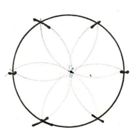
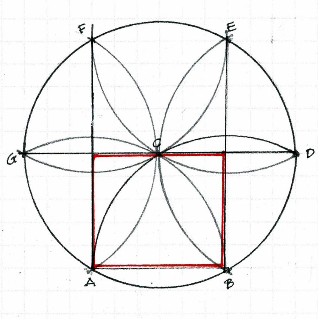
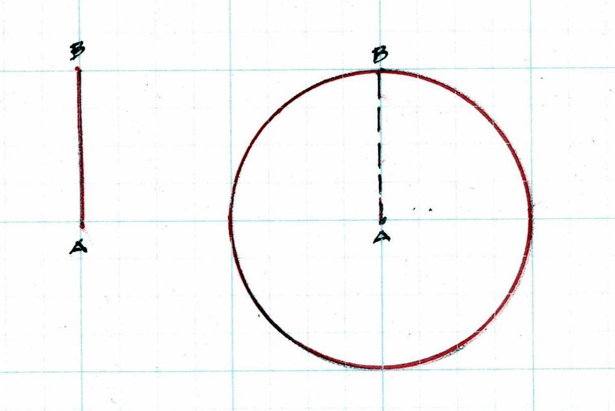
** A square can be laid out by a compass. Square corners can be determined and proved by a daisy wheel. Here is the visual explanation: the width A-B as the radius of the circle and locates the 6 points of the circumference A, B, C, D, E, F, G. Then: Lines A-F and B-E are perpendicular to A-B. Line G-C locates the end (west) wall of the Parlor.
Tuesday, October 3, 2023
Teaching Practical Geometry
Several educators, curious about Practical Geometry, have asked me how I would share this geometry in the classroom. This post is an introduction to how I would begin.
In September, 2023, I presented 3 workshops at IPTW, the International Preservation Trades Workshops.* The last day was open to the public. About 10 people, aged 10-70+, came to learn about Practical Geometry. Some had never held a compass.
Here is what we did:
We drew circles with compasses. Then we divided the circumferences into 6 equal parts and connected the points to make rectangles and squares. We used no numbers.
We explored the design and layout tools a carpenter would have had before the Industrial Revolution: the compass, a line and a scribe. We talked about how those tools were used and are still used. We compared cubits (the length from your elbow to your longest finger). We set carpenter's dividers for a day's work by the radius or the diameter of a daisy wheel. One of the participants taught the others how to snap a chalk line.
I brought my daisy wheel with me. It was scribed into a 9 ft tall board which was once sheathing on Vermont barn, c.1780. The barn was deconstructed about 10 years ago. The deconstruction contractor gave me the board.
I showed them the floor plan of one of the early Virginia folk houses recorded by Henry Glassie,** which used the geometry we had drawn.
I shared a few pictures including this house whose plan we had just laid out.
That image introduced the class to the chimney wing. Its plan would have used the 3/4/5 rectangle to make sure the wing was parallel to the house so that all the roof framing could be cut the same length.
I showed the group a Menagery, a retreat intended for an English gentleman's estate, designed by James Gibb's ***, c. 1720.
The wings are laid out in the same way, using the 3/4/5 rectangle. Here it is because the rough laid stone on the exterior would have made an accurate layout and construction difficult.
Then the class learned about the 'star', the Lines, in the center of the Menagery. Those are also the lines on our cellphones which help us edit images, known by artists as the Rule of Thirds.
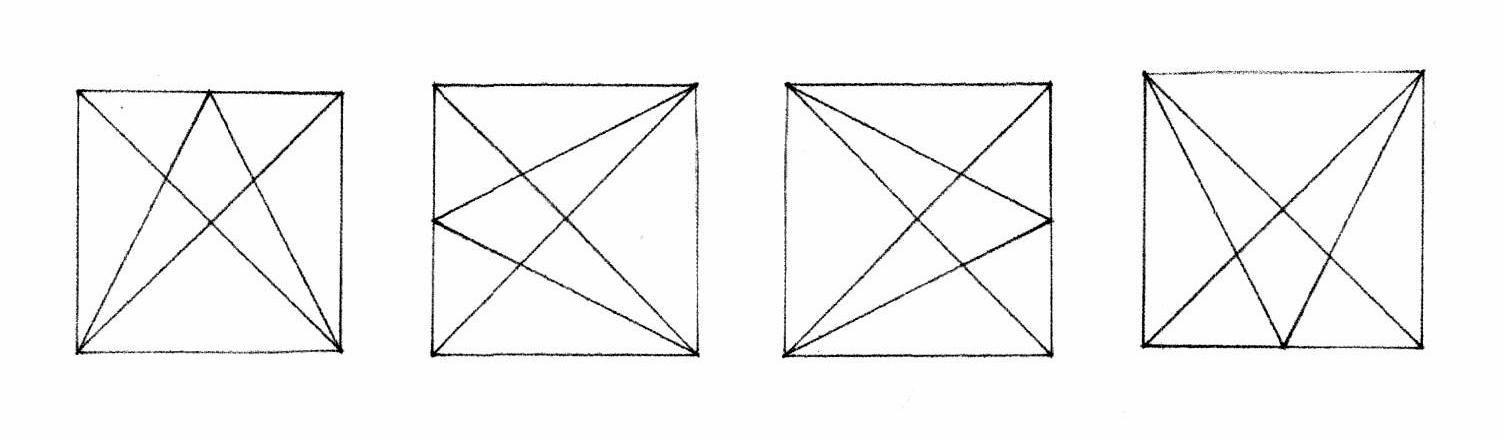
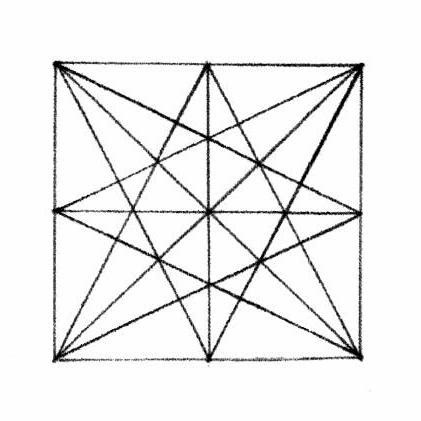
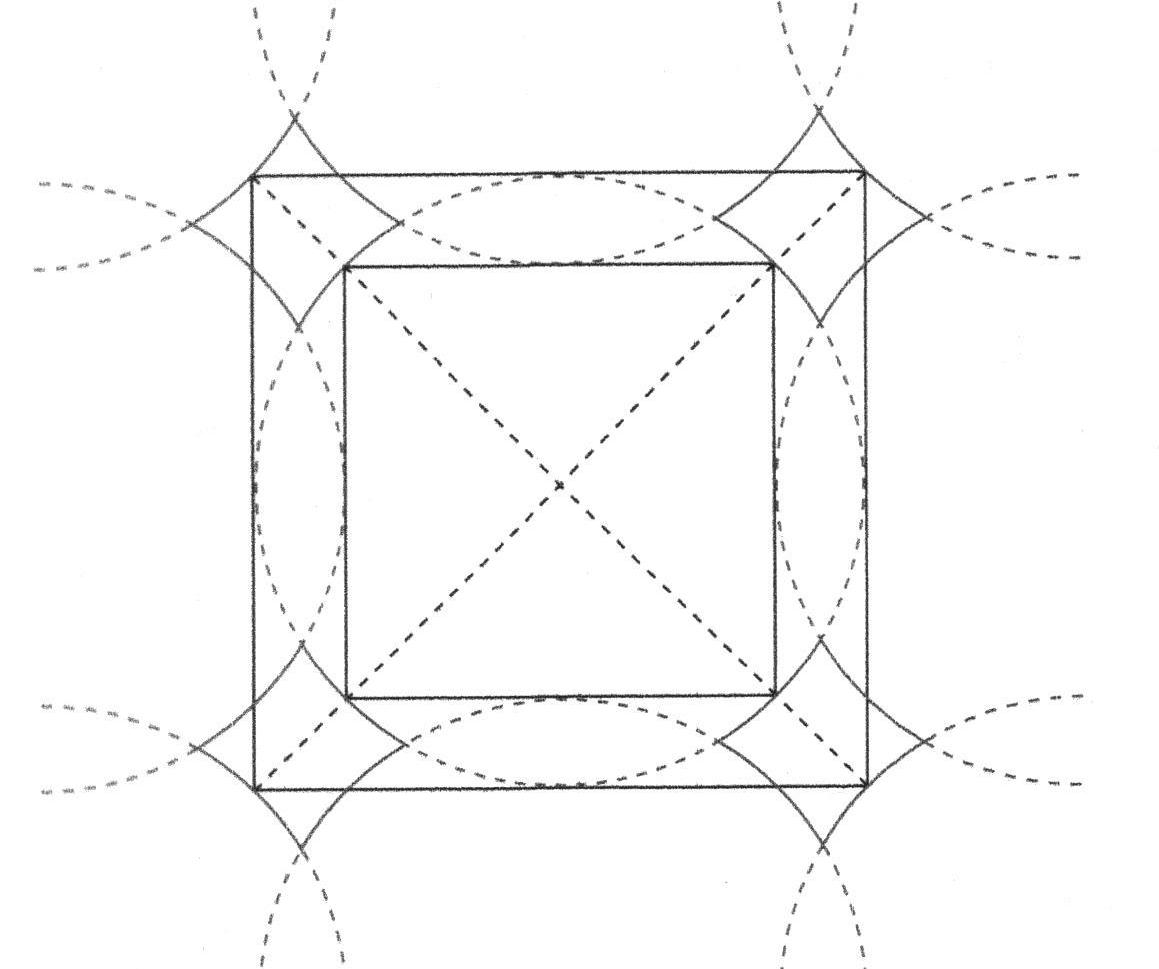
Here is the geometry: the diagonal of the square and the Lines from the ends of one side (the corners) to the middle of the opposite side. The pattern is turned 4 times.
Where the lines cross are points. 2 points connected are a line. That line is always straight.
Here, the points divide the large square into 9 small squares - the diagram used on cellphones - or 3 equal rectangles.
There are also 4 squares within the large square. If their diagonals are drawn, the large square can be divided into 16 small squares or 4 equal rectangles.
The Lines on the elevation for this brick house tell the mason where the sides of the door and window openings are. On the plan the Lines show the fireplace edges and the placement of the interior walls.
The drawing is Plate 56 in Owen Biddle's pattern book, The Young Carpenter’s Assistant, published in 1805, by Benjamin Johnson, Philadelphia.
I ended with these Lines in Sebastiano Serlio's Book I, c. 1540. It explains where to place a door in a castle wall. He ends Book I: On Geometry, " However, honest reader, although the things resulting from the various intersections of lines is infinite, to avoid being long-winded I shall come to an end."
This was more than enough for one 75 minute session.
Several shorter lessons would have been easier for everyone. There was very little time for questions, more examples, or in-depth understanding.

For more information: In 2020, I wrote 7 posts entitled 'Lessons' for students of all ages.
https://www.jgrarchitect.com/2020/04/lessons.html
*The 25th International Preservation Workshops were held this year in Frederick, MD, at the Hargett Farm which will become the Historic Preservation Trade Center for the National Park Service. See the Preservation Trades Network website, ptn.org, for more information.
** Henry Glassie,. Folk Housing in Middle Virginia, U of Tennessee Press: Knoxville, 1979
*** James Gibbs, Book on Architecture, London, 1728, Dover reprint
**** Sebastiano Serlio . On Architecture, Lyon, France 1530, translated in1611, on-line and translated by Vaughan Hart and Peter Hicks, 1996, Yale University Press, New Haven
To read more about this diagram see:
https://www.jgrarchitect.com/2022/10/serlios-lines.html
Wednesday, June 7, 2023
That daisy wheel you found? Please trace it for me.
If you found a daisy wheel scribed on an old building, please trace it, copy it, and send me the full scale image with a note about where it was found, on what kind of building.
I want to compare daisy wheels and measure their diameters. Here's why.
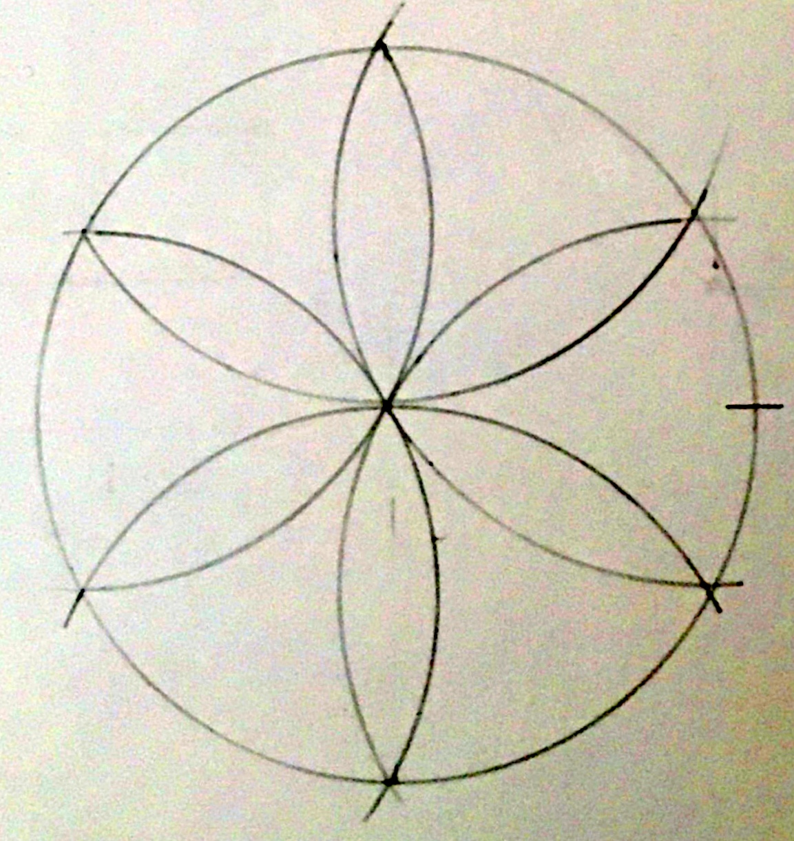
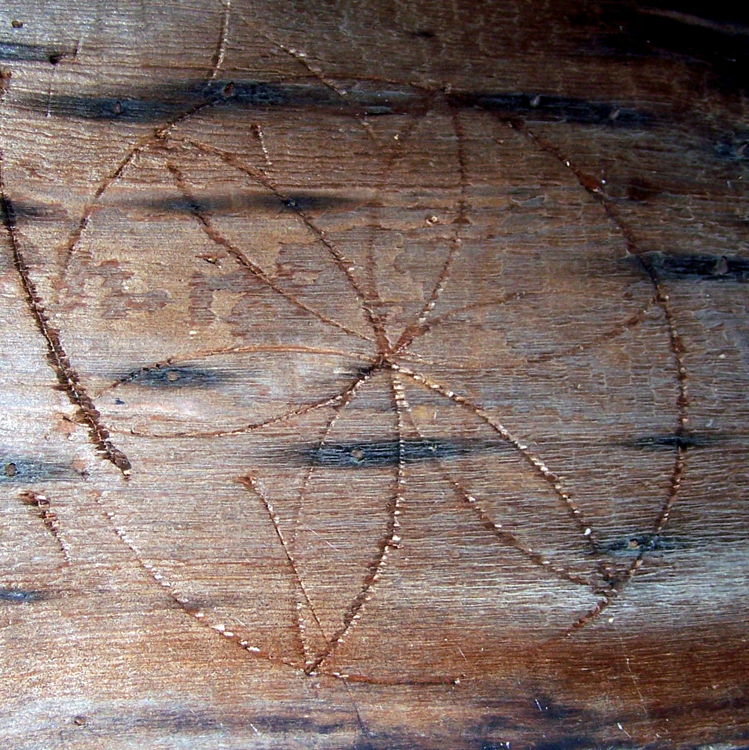
The daisy wheels we find today were scribed with a compass on posts, on beams, sheathing, walls: a circle with 6 points, 6 petals, evenly spaced, drawn using the radius of the circle.
200 years ago they were a practical tool for layout and design, simple geometry, easy to use and true - accurate - in a world without fixed dimensions. Standardized dimensions came with interchangeable parts which we didn't need until the Industrial Revolution.
Daisy wheels have been noted and copied. Rarely have we measured their diameters. Are the diameters of daisy wheels a scale, just as the notation- 1/4"=1'O" - is a scale? Maybe, But I can't tell from only 3 examples. I need to check a lot more!
This is my daisy wheel and its 9 ft. long board. It was part of an outbuilding of a barn in Vermont.
The center of the wheel is 46" from the floor, a good height for a workman setting his basic dimension for his compass width (the diameter of the daisy wheel) as he began work and checking it as he needed throughout the day.
It was also useful information for those who came later, expanding or repairing the farm complex.
My daisy wheel was easy to find. However, many are discovered in obscure places, on beams and roof sheathing.
As a frame was cut that piece of the frame (usually sheathing) was a notice board. When the frame was raised, the wheel had served its purpose. The sheathing however, cut by hand and water power, was too valuable to discard. It became part of the frame.
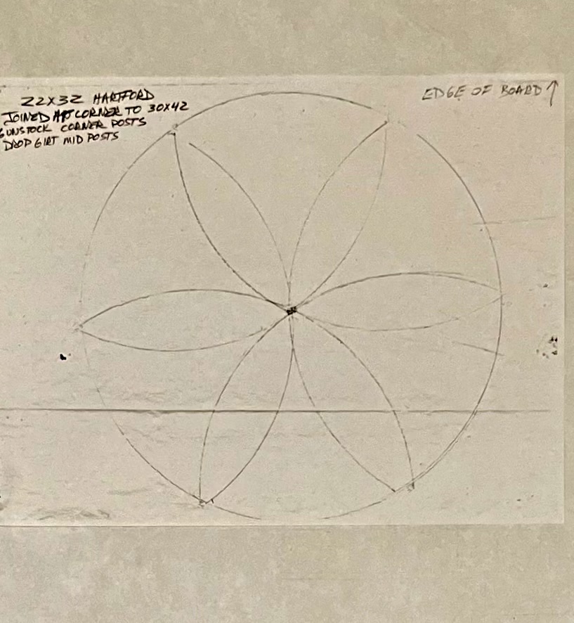
This daisy wheel was on roof sheathing of a barn in upstate New York, built c. 1795.
Unlike the daisy wheel above which has deep holes at its center and at the outer points of the petals as they meet the circumference of the circle, this wheel is cleaner, probably used only for this barn, not the larger barn complex around it.
Here is a tracing of it.
Both of these daisy wheels measure 8" + a smidgen. The depth and age of the scribe's grove makes precision difficult. However: 8.25" x 2 = 16.5". 16.5" x12 is a rod, 16.5 feet.
The rods laid out by stepping off these 2 daisy wheels' diameters might differ from each other by several inches. But each frame would be consistent within itself.
A rod was a common dimension in England. It was also called a 'pole' and a 'perch'. Land surveyors still measure land in rods today.
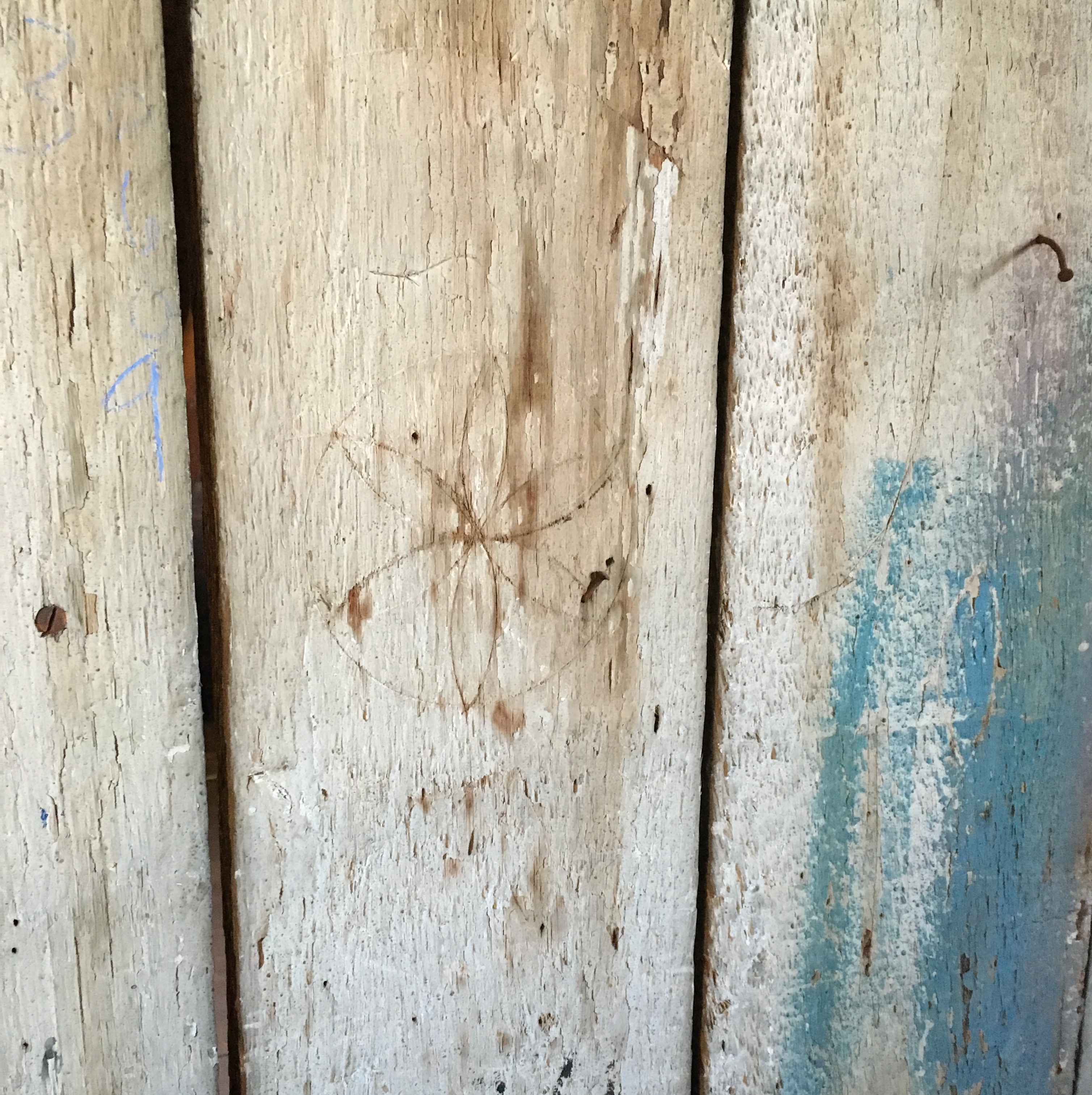
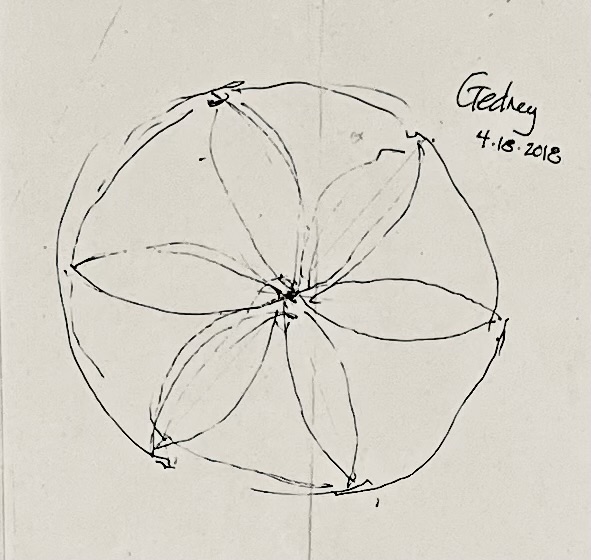
This daisy wheel is on the interior side of the sheathing on the second floor of the Gedney House in Salem, Massachusetts, built in 1665, expanded in 1712, and 1800, The house is now owned by Historic New England.
The daisy wheel is quite small.
Its diameter is 5.5". 5.5" x 3 = 16.5". 16.5" x 12 = a rod.
The neat, small ones which we find may be the signature of a trained master carpenter or mason. Laurie Smith (English Geometer, 1936- 2021) showed me one carved into a stone mantle. He had found that the geometry governed the design and was also probably a signature.
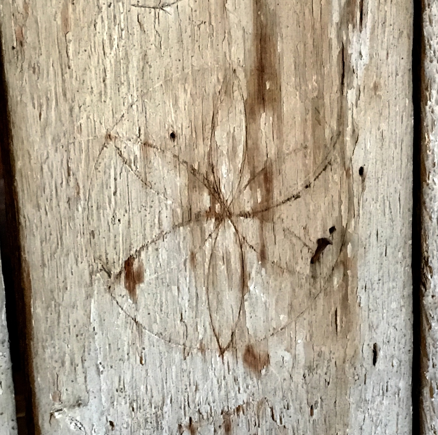
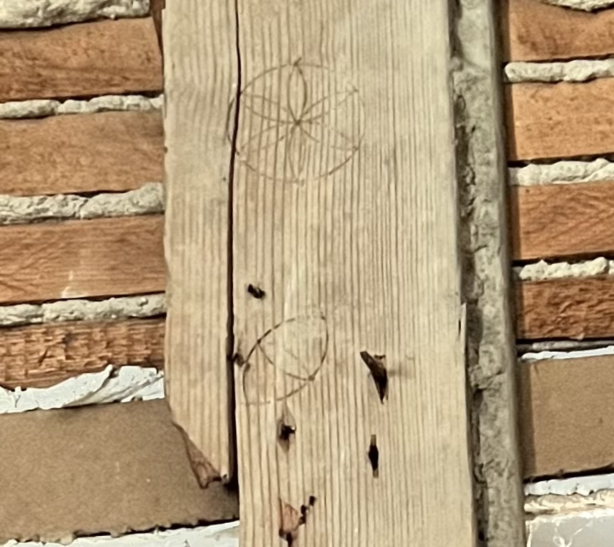
This one comes from the Beatty-Cramer House in Maryland.The wheel diameter is 3". It and the 'eye' below it might be Masonic symbols of God and Truth, as geometry was known to be true.
The understanding that geometry is 'true' was not part of my high school geometry class. I learned that from carpenters.
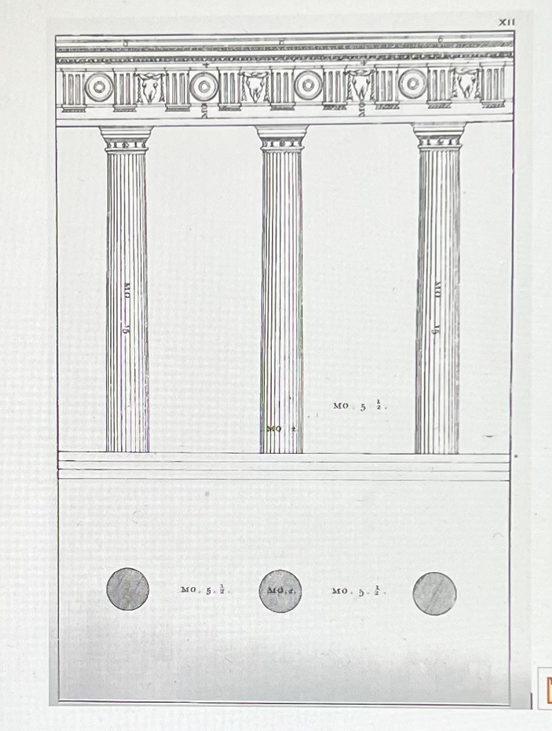
Palladio wrote c.1570 that he would use the diameter of a column as his 'module', his measure for his work. Here's his drawing:
The column is a circle. It is laid out with a compass, Its diameter, stepped off using a compass, is the module: it measures the distance between the columns. The scribed daisy wheels that we find today are also modules.
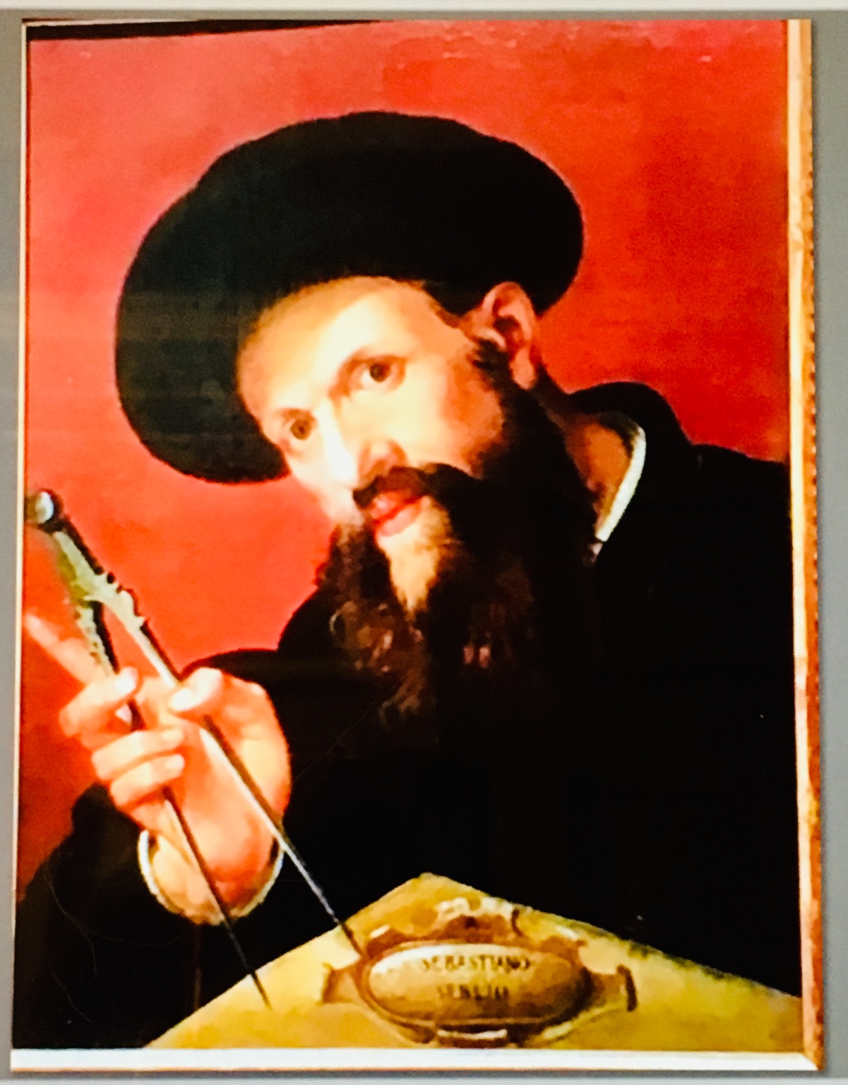
Here he is, holding his compass.
Daisy wheels are said to be apotropaic. However I have not yet read a record made by someone of the period noting the deliberate addition of a daisy wheel to a building to ward off evil. I am skeptical.
Saturday, April 1, 2023
Serlio Studies a Roman Temple
Sebastiano Serlio, 1475-1554, wrote 7 books 'On Architecture and Perspective' .
A contemporary of Palladio and Vignola, he spent much of his career in France working for King Francois I. The first part of his treatise was published in 1537.
Here he is with his compass.
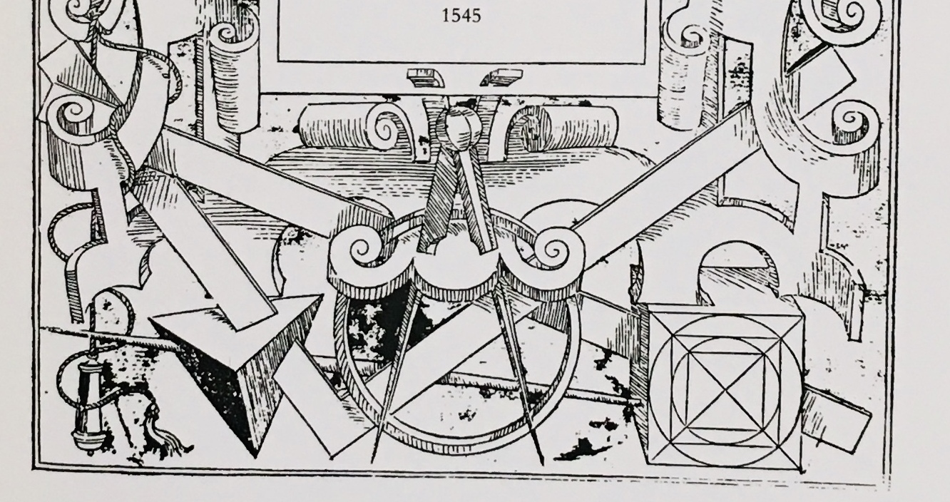
The cover of Book I includes this drawing of builders' tools across the bottom, including a tetrahedron and a cube with diagonals, squares and circles on its face, in the right corner.*
What's the cube about? I didn't know, but I am beginning to find out.
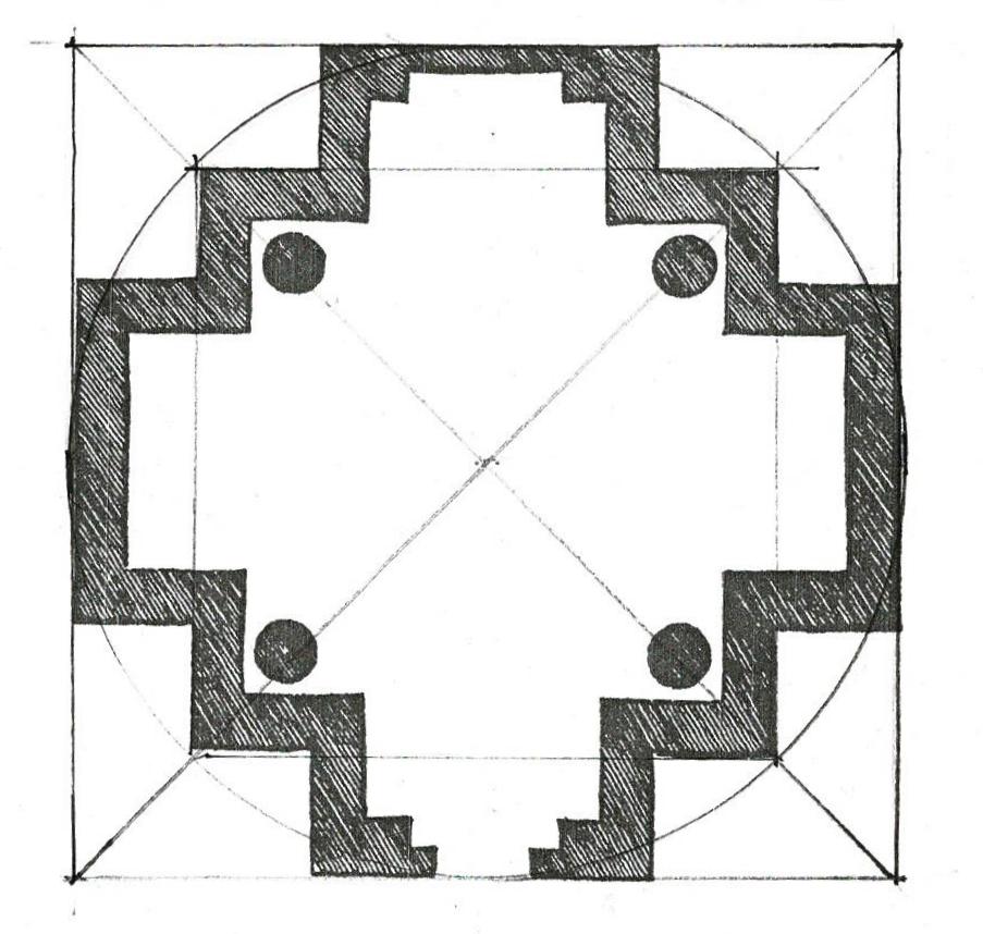
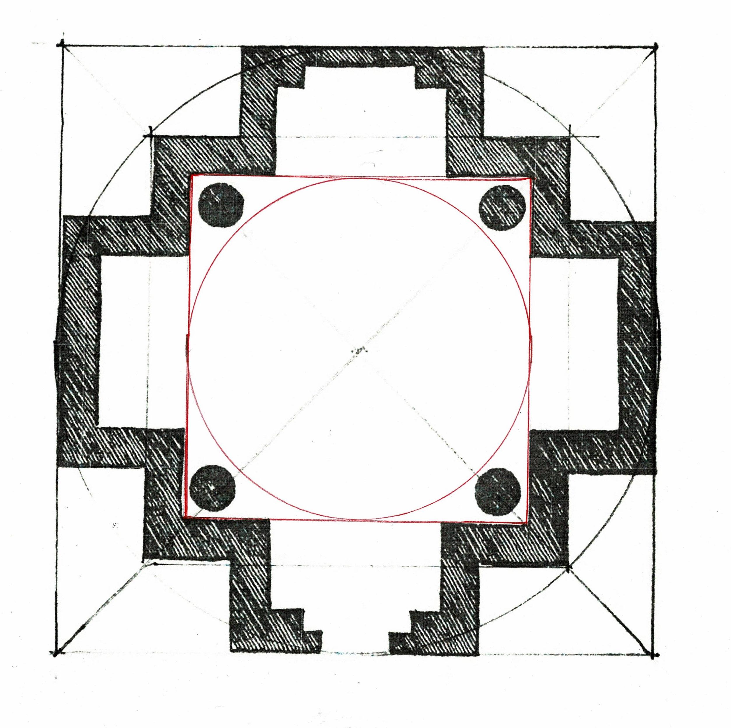
Book III, On Antiquities includes the illustration and measured plan of this temple outside of Rome, now thought to be the Sepulchre of the Cercenni.
He writes that it was "built partly of brick, partly of marble and to a large extent ruinous."
To read the geometry look at
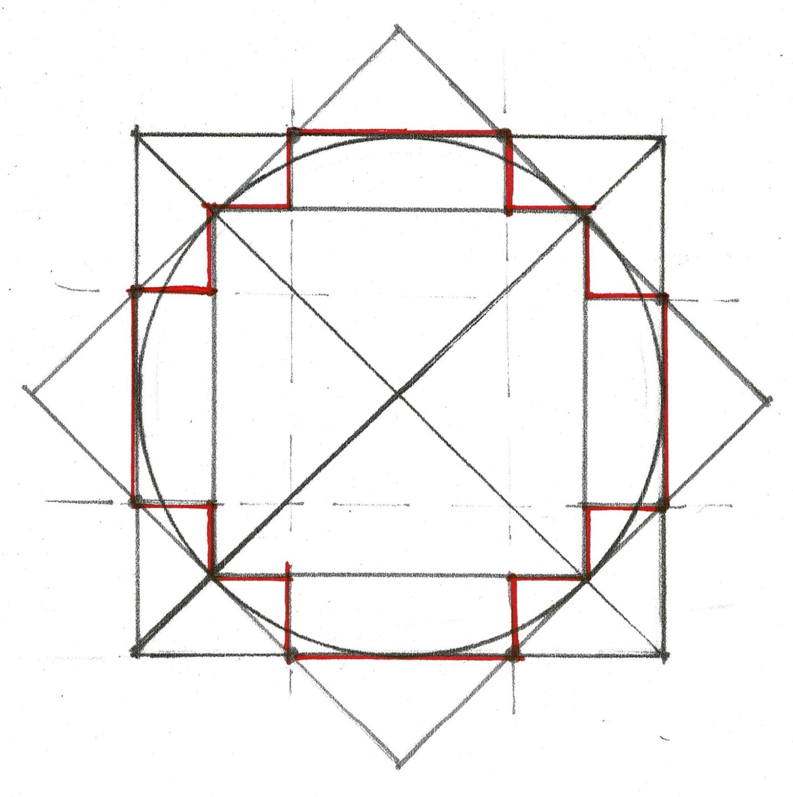
1) the square, its diagonals which mark the outside of the temple including the bays;
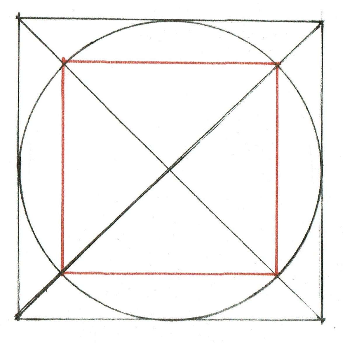
2) the circle which fits within the square which mark the corners of the temple itself;
3) the square which fits within the circle locating the outside of the walls.
Rotate the first square 90* to make an 8 pointed star. The intersections of the stars points mark the outside corners of the bays.
The inner square (barely visible in red) was not used.
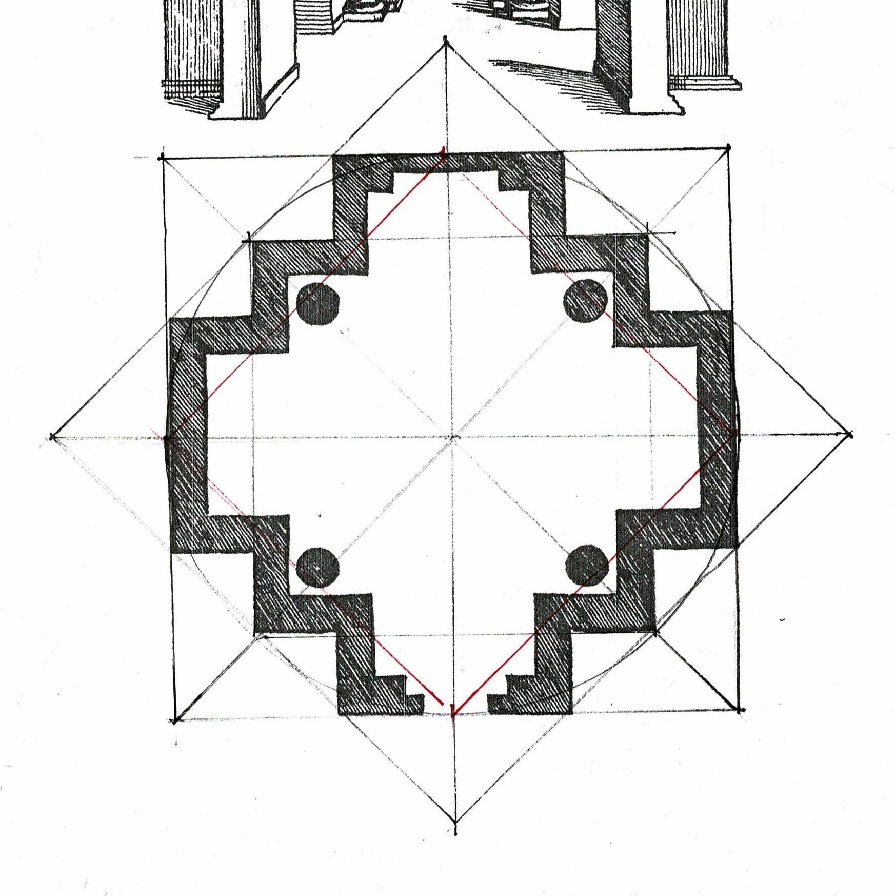
Here is the how the master mason could have used geometry to lay out the plan on site.
The red square was probably the beginning. It is the foot print for the walls.Then the diagonals, the circle around it, and the next square were added. These set the depth of the bays.
Next the outer square was rotated. It crossed the large square at 8 points. Those points when joined laid out the width of the bays.
The lines set the perimeter of the plan.
The mason had his foundation plan and could set his lines.
I usually find that the interior geometry of a masonry building is laid out from the inner side of the walls. This is practical: reaching over the walls with lines would not have been easy nor accurate.
The square and its circle neatly locate the columns which support the vaulting.
Thursday, February 2, 2023
Practical Geometry at Mud University, Cambridge, NY, March 3-4
Announcement!
I'm giving a class on Practical Geometry at Mud University, in Cambridge, NY, on March 3-4, 2023.
Their website is at the end of this post.*
Just in time for mud season! Come learn about practical geometry at Mud University.
FREE and FUN! With a fabulous instructor: me.
Anyone who's curious is welcome, no math or drawing skill needed.
March 3, First meeting: I will introduce geometry as practical knowledge well understood until about 1950. We will use compasses to layout daisy wheels.
March 4, Second meeting: we will draw the patterns, hands-on with compasses.
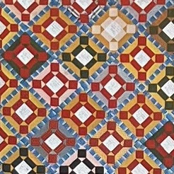
Here's a diagram - the square and its circle.
It is the language for the pattern of a quilt
(dated 1847)
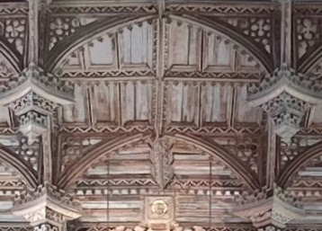
and the roof structure for St. David's Cathedral in Wales (c. 1550).
I'll talk about what Practical Geometry was/is using a Power Point presentation to show the history of the use of geometry in construction and design.
You will see how our ancestors, weavers, quilters, cabinet makers and builders used geometry for design and construction. I will mention drawings, paintings, and illustrations, including how our cell phones superimpose the rule of thirds over our snap shots.
Ask me if you have questions. Or just sign up.
I look forward to seeing you there. Jane
St. David's Cathedral and geometric pattern :
Smith, Laurie, The Geometrical Design of St. David’s Cathedral Nave Ceiling, A Geometer’ Perspective,
The Geometrical Design Works, 2017, printed Exeter, UK. and others.
Thursday, January 19, 2023
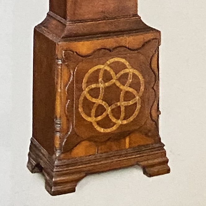
A Lancaster Clock Case: its geometric design
The Dietrick American Foundation published an article about a Lancaster clock case, researched and written by Christopher Storb, in July 2022.* It was forwarded to me by Craig Farrow, Cabinet Maker.** He knew I would be interested.
The Foundation wrote that it "intended [such articles] as a type of crowd sourcing, where responses and information shared by readers can inform research." I am happy to respond, to try this way of sharing information, to see if it can be successful.
As my research on the use of geometry in construction - Practical Geometry - is not well known or understood, I have written this post as an introduction.
I will write to Christopher Storb when I publish this analysis. I look forward to his reply and the information from others who have responded.
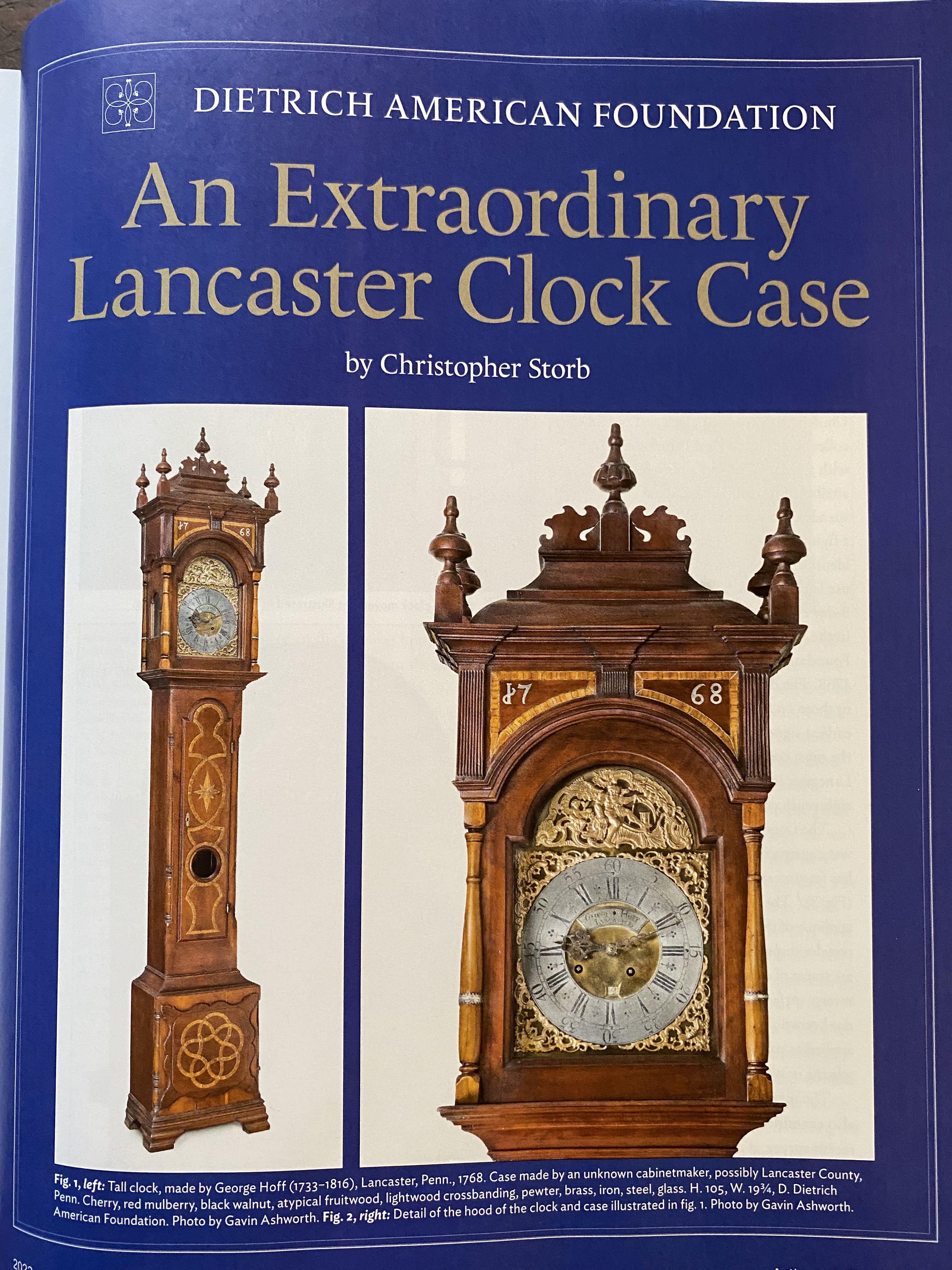
The article is fascinating with clear images and explanations.
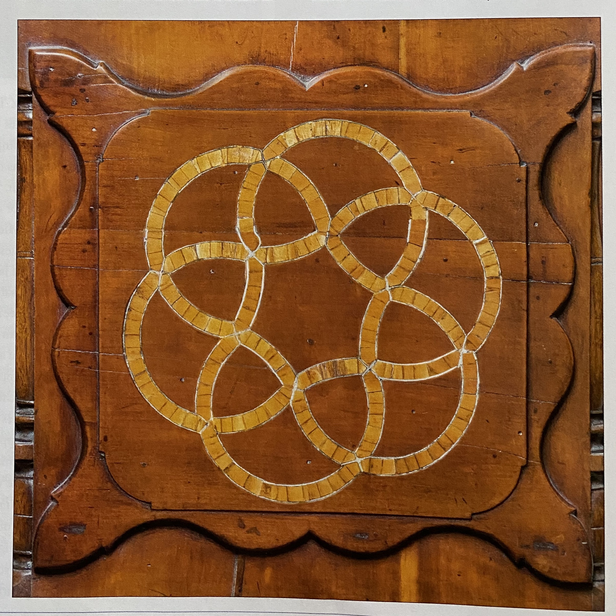
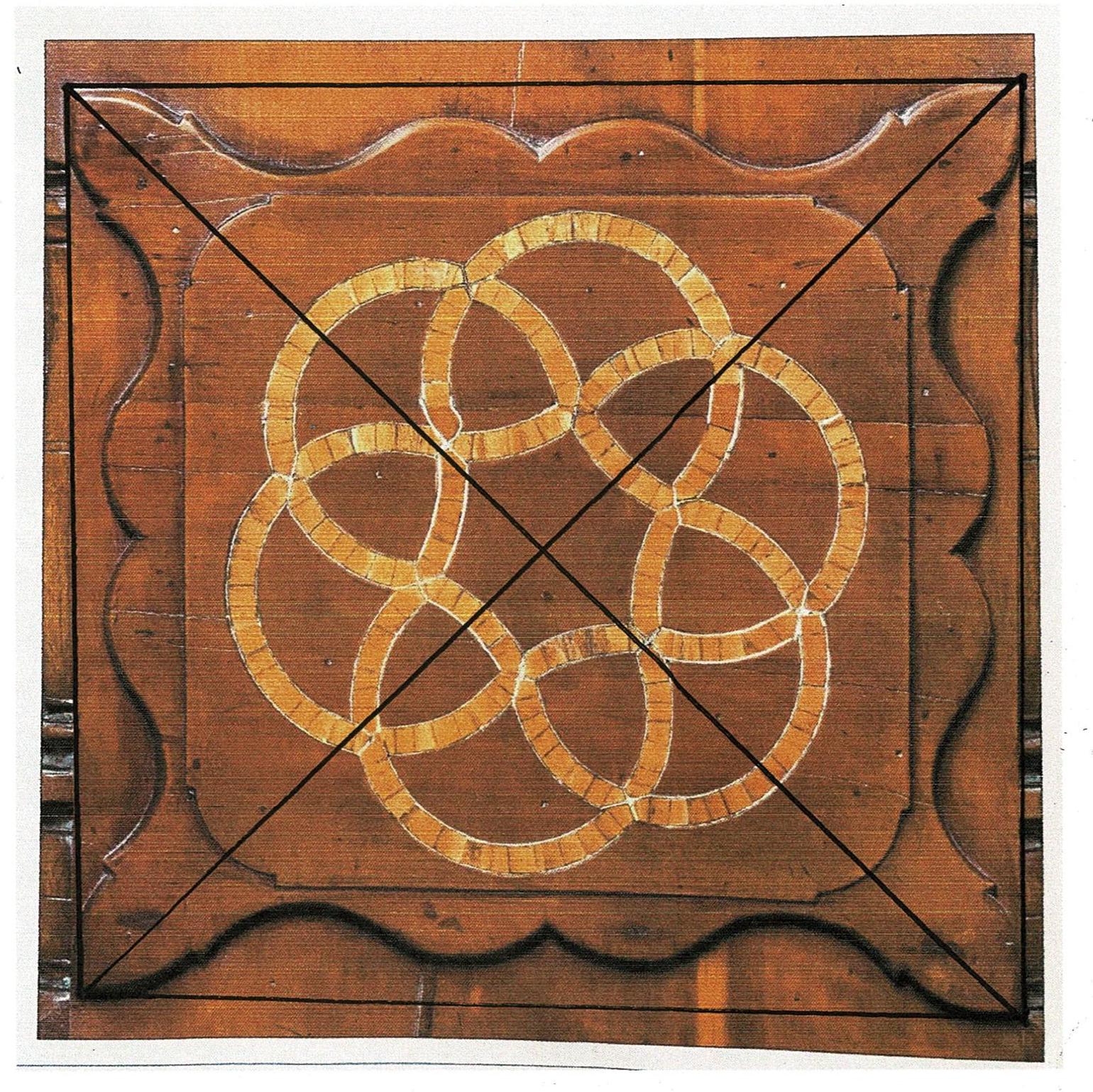
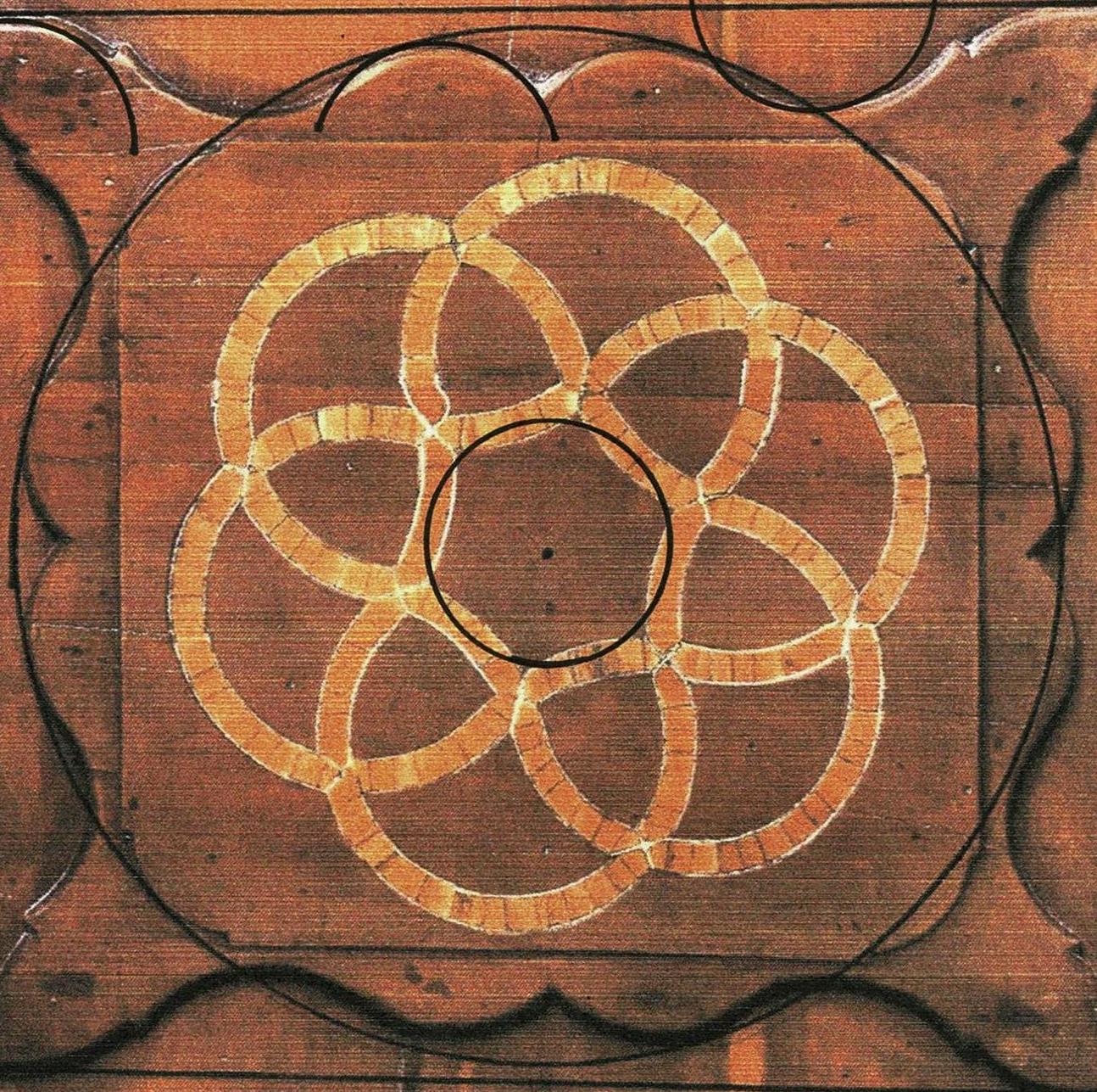
I especially liked the the medallion at the base of the clock case and was delighted with the cabinet maker's tilt of the knot. I appreciated Christopher Storb's clear analysis of the geometry of the knot as intertwined hourglasses rotated to "create the illusion that the design is in motion, mirroring the actual rotation of the hands of the clock dial above."
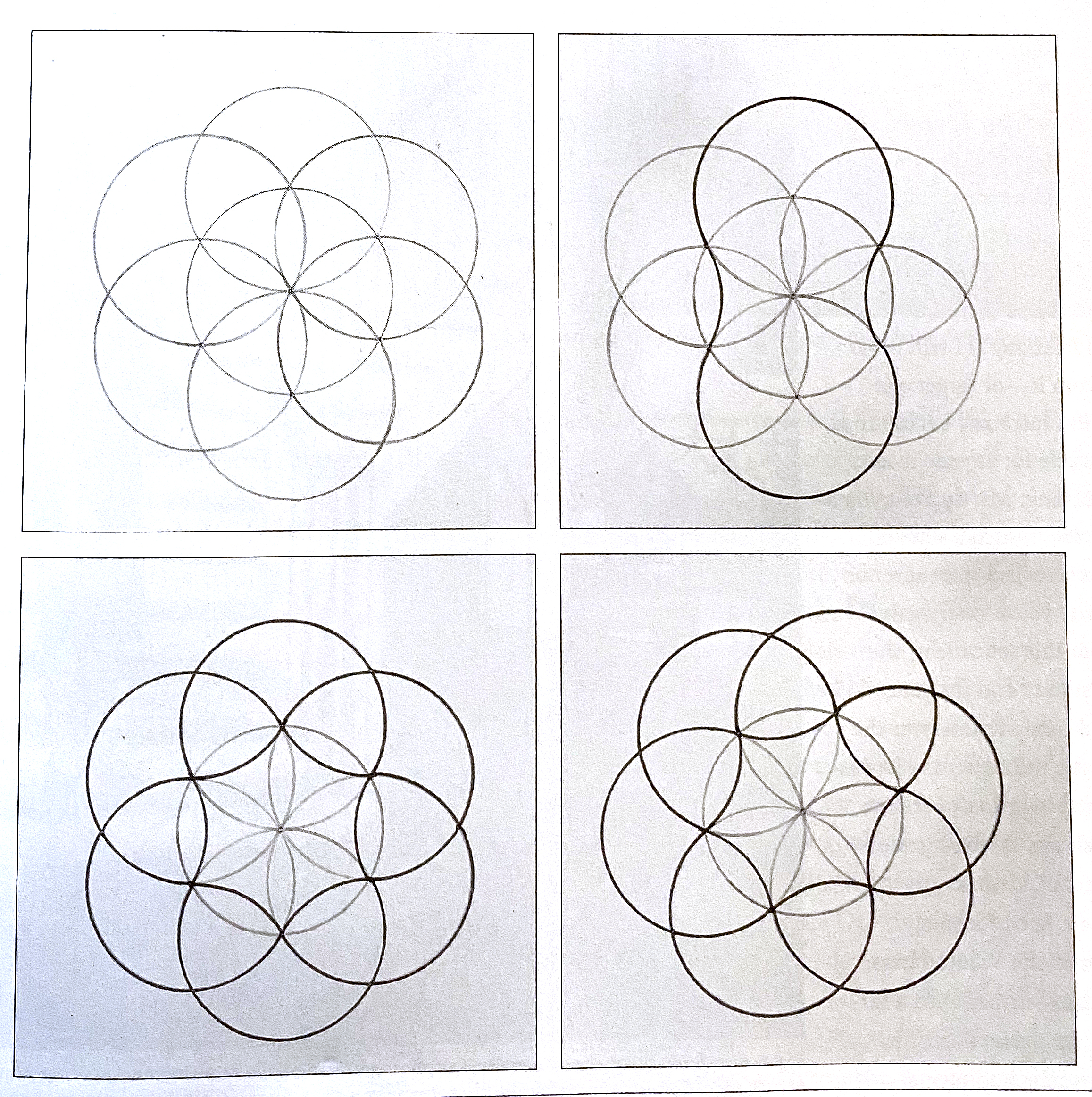
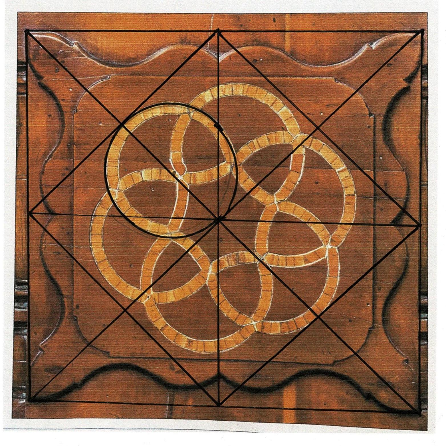
Here is the geometry as drawn by Christopher Storb: the daisy wheel and its 6 outer circles, the lines of the parts of the geometry used on the clock outlined for clarity and then the pattern rotated to fit the diagonal, upper left to lower right.
I saw that the geometry governed the design of the whole lower panel, not just the knot.
I decided to map it.
The photograph in the article is not quite square. The image of the knot and its panel is slightly skewed; the diagrams drawn over the image are not quite true. Therefore I have drawn the geometry separately.
See the lower edge: there is a space below image on the lower left corner, but almost none on the lower right. That's enough to skew the geometry.
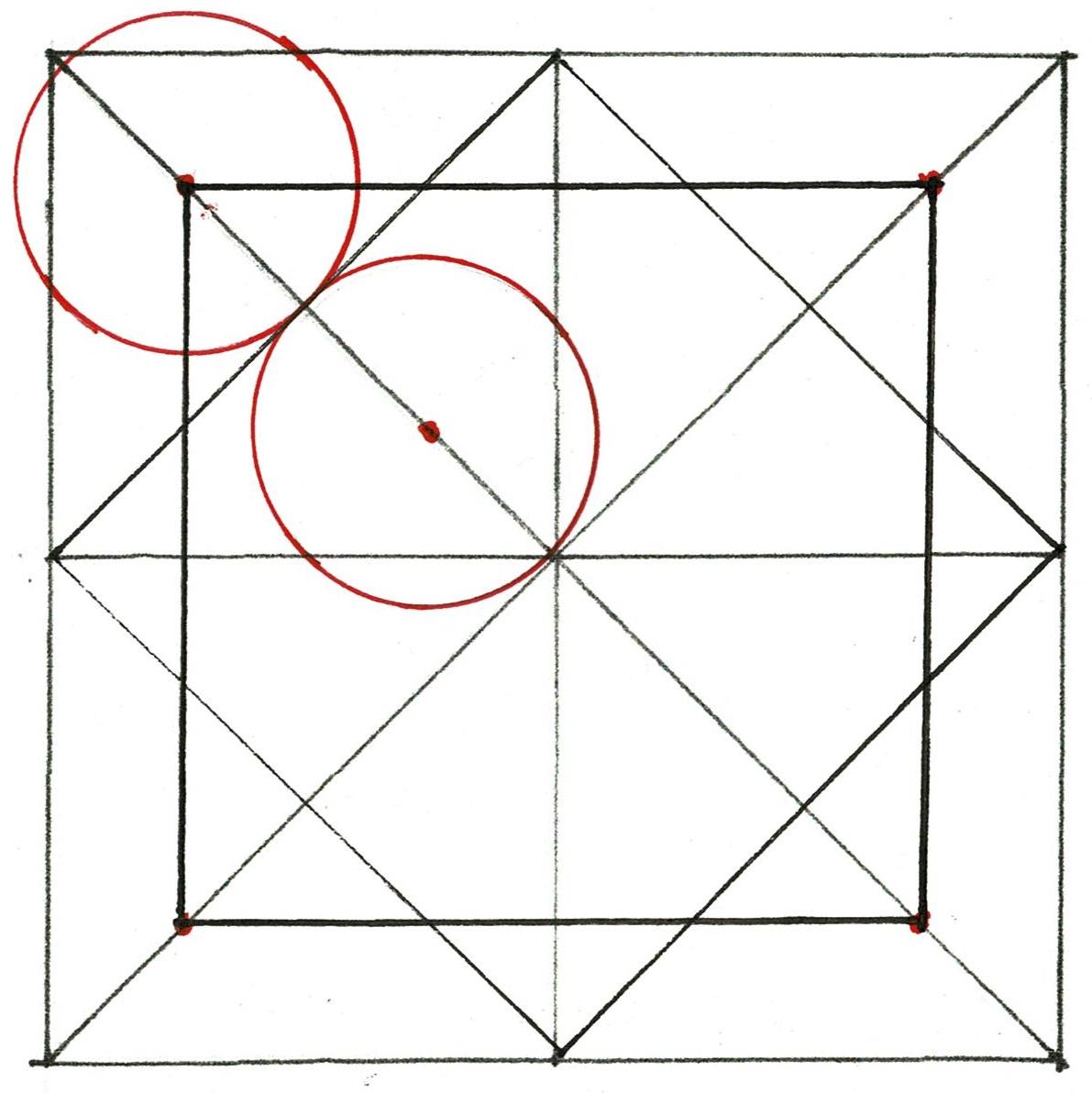
I began with the panel which is the front of the base. It is a square.
I added the diagonals.
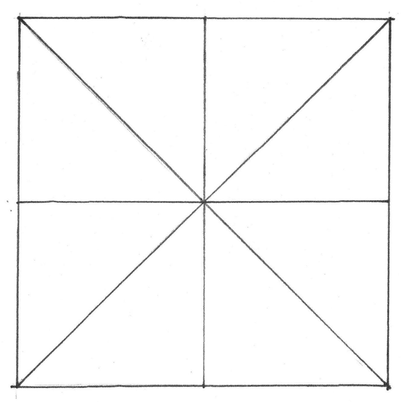
Then I divided the sides in half, vertically and horizontally. ***
Here is the geometry as laid out by compass and straight edge.
The cabinet maker did not need to use numbers. Each line came from the basic shape, that first square.
The horizontal and vertical lines bisect the scalloped edge.
Every line crosses the others in the center.
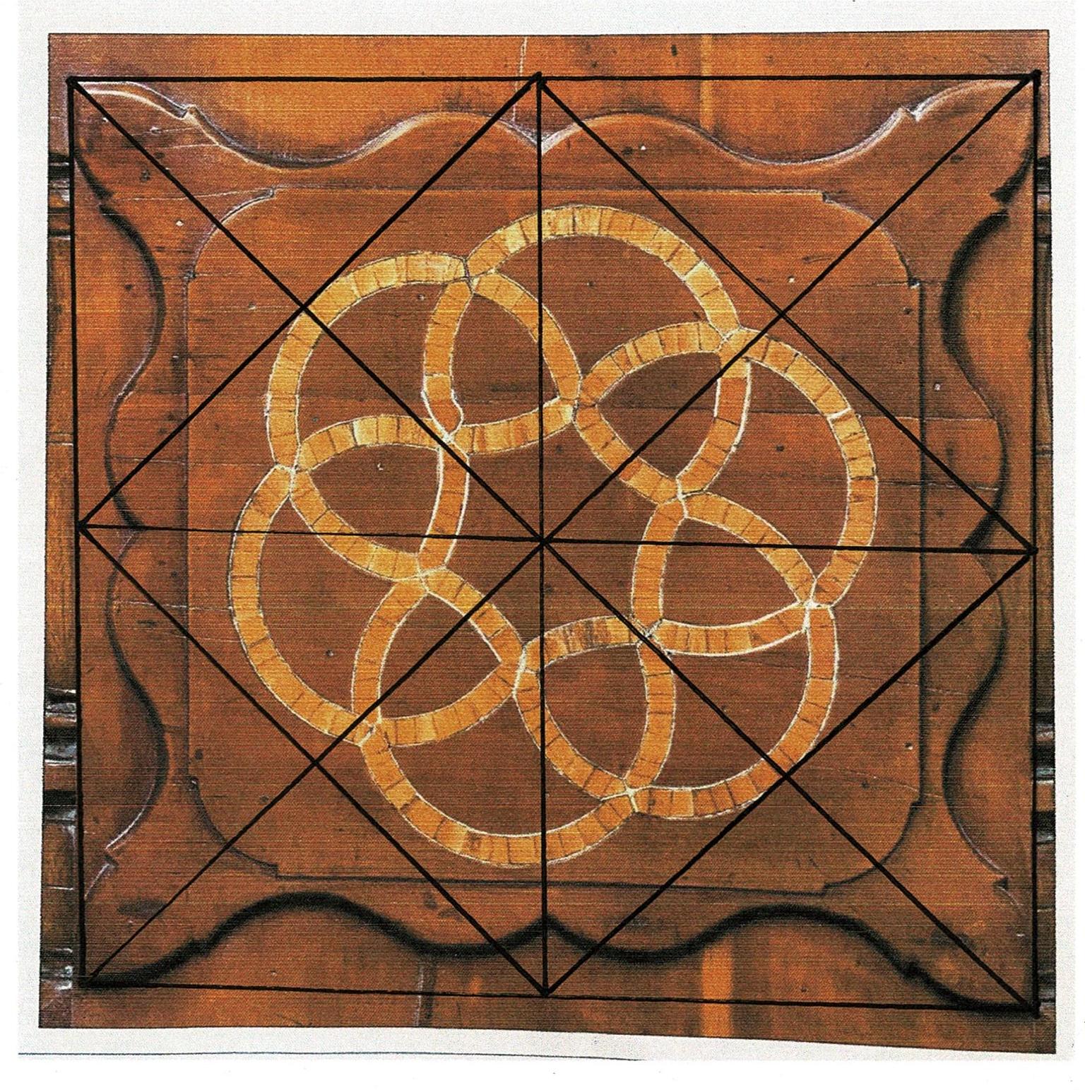
From those lines several others are easy to add. The sides of the smaller rotated square run from center point to center point.
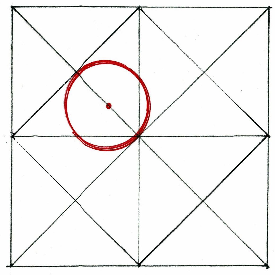
A small circle - with a diameter the distance from the center of the design to the inner rotated square - can be added.
That small circle is the first circle of the knot, located by the geometry of the face - its diameter is determined by the squares.
The rest of the knot can be laid out with a compass as shown in Christopher Storb's diagrams.
The cabinet maker did not need to rotate his diagram. The knot began on the slope of the diagonal.
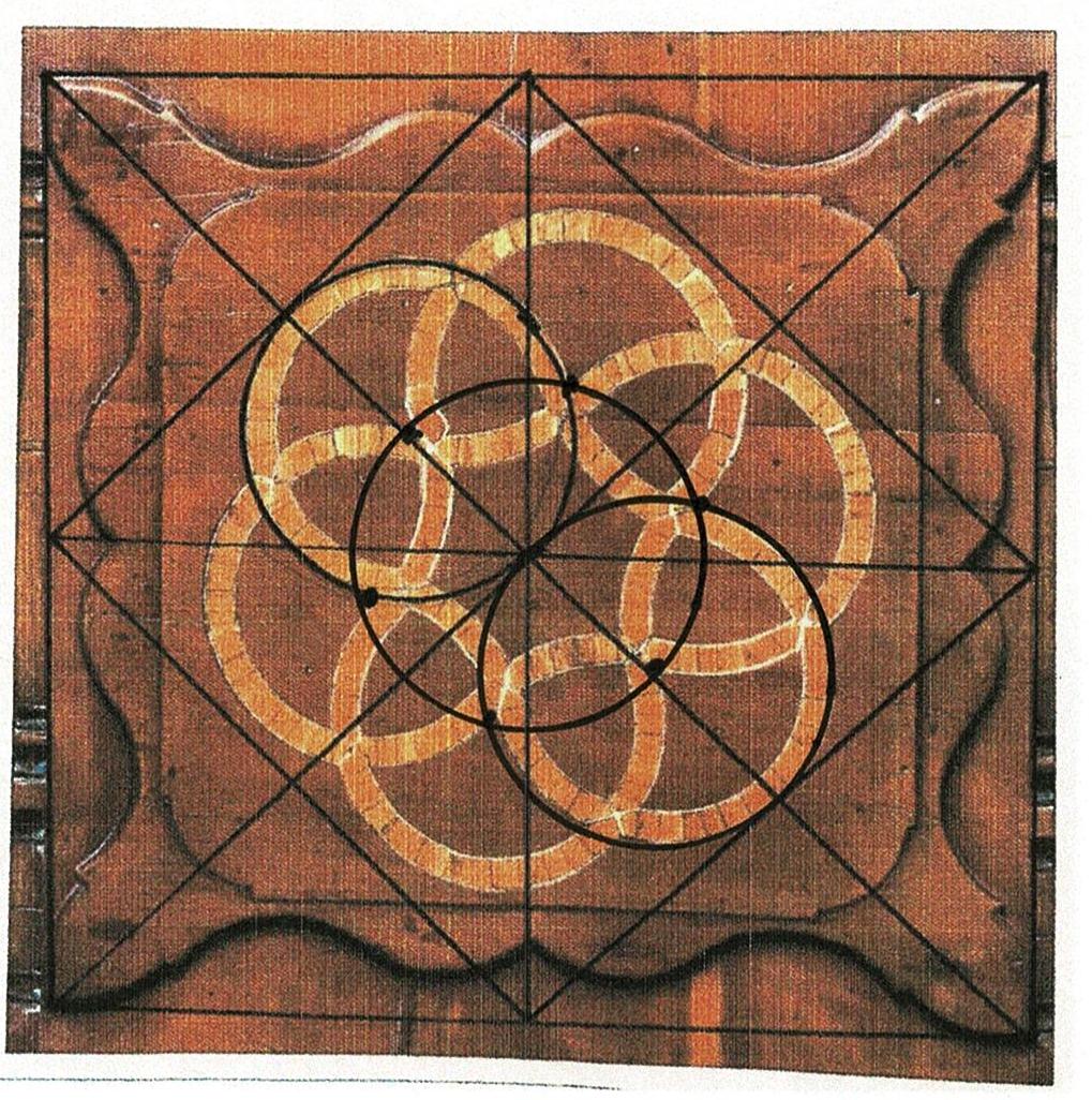
Here is the vertical hour glass image, in the center, as it is in the upper right of Christopher Storb's diagrams. 6 more circles can be added around the outer ring of the hour glass layout.
I have only drawn 2. Their arcs are the inner curves of the hour glass shape.
The square shield surrounding the knot comes from the circles that radiate out from the knot on the diagonals. Their centers are the corners of the square. The cabinet maker did not need to draw those circles. His compass was already open to the circle's radius and could mark the corners of the square.
I have added the upper left circle in red, then the 3 other centers of the circles - the corners of the square - as red points on the diagonals.
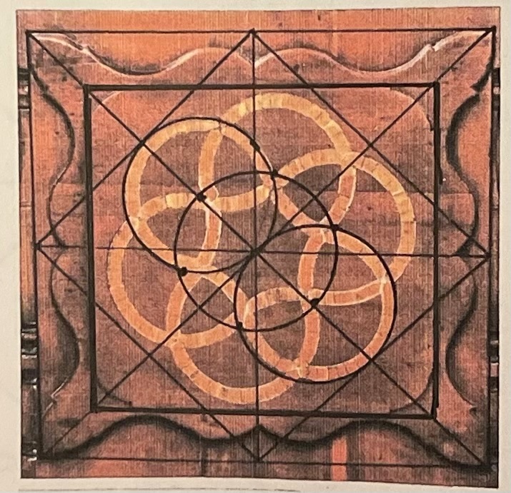
Here is the layout of all the squares of the design.
They are governed by the lines which begin with the exterior square of the clock case's base.
The square (as drawn here) of the shield confines the knot. It is static but the knot is fluid.
The shield's circle which surrounds the square, is also a perfect, stable shape. The knot implies movement and change while the circle is constant, never changing. The circle constrains the knot's curves just as the square does.
The diagrams are the forms for the design. They were the beginning. Then the cabinet maker played with the shapes.
His solution was to compliment the knot by curving the corners of the square with the circumference of the circle. He loosened that circumference by adding the scallops and fins.
The flourishes - the scallops and fins - are laid out by the arc of the radius of the inner circle of the knot, a smaller circle which comes from the width of the wood and pewter bands.
The shield becomes not a constraint but a backdrop, a commentary. Both the square with its softened corners and the circle behind it with its horns and scallops present to the viewer that remarkable knot with its pewter ribbon.
What knowledge and skill this cabinet maker had!
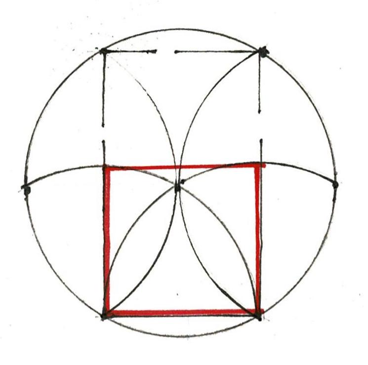
*** dividing a square in quarters using a compass:
This diagram was published in pattern books written to instruct apprentices. The square with its arcs has 2 points both horizontally and vertically. The lines of these points divide the square into quarters.
Tuesday, January 10, 2023
Geometry in Construction = Practical Geometry
Geometry in construction = practical geometry.
Does that seem strange, a philosophical stretch? As recently as the 1930's it was widely understood, commonplace. Since the 1950's, geometry has been taught as precise, logical, beautiful, magical, amazing. But practical? Barely. Today the idea is usually met with skepticism.
However, you who read my blog know this is what I study: what those builders know about geometry and how did they use it?
Euclid's geometry starts with a Point which has no dimensions. Two points make a Line - 1 dimension. 3 make a Plane - 2 dimensions.
4 points make an object - 3 dimensions.
How can this geometry be practical?
A Line laid out between 2 points will always be straight.
A Line drawn by hand might curve; a Line marked by snapping a length of twine cannot curve. This is the beginning: it will be true. If the geometry is not accurate it will not be practical.
The Line A-B can become a radius. The radius can draw a circle.
Whether the circle is drawn with a compass set to the length of the radius. or by hand with a length of twine, it will close if the the work is accurate. If the circle does not close upon itself it is not true. At every step of the layout if the geometry doesn't hold, the designer will know to stop and correct the drawing.
The radius of the circle always divides the circumference of the circle into 6 parts. If the points on the circle, marked by swinging the arc of the radius, are not spaced accurately they will not end exactly where they began.
They will not be true. The work cannot proceed. These 6 points on this daisy wheel are not quite accurate.
Note that the daisy petals' shapes are not identical; the points are not equidistant.
If I measured the diameters, petal to petal, they would not match. I was not careful enough.
The 6 points, joined with lines, can be used in construction.
The rectangles that come from the 6 points can be proved by their diagonals. If they match, the rectangle will have 90* corners and be true. If the diagonals do not match the shape is not a rectangle.
A building needs to be stable, whatever materials it is made from, whatever form it takes. For simple vernacular housing the circle was the practical geometry needed to erect a stable, sturdy dwelling.
The layout tools available to the builder of the Lesser Dabney House* in rural Virginia, c. 1740, were twine, some pegs, a straight edge, some chalk or soot so the twine could mark a line, perhaps a scribe, a compass.
He could have laid out this house with the first 4. A peg could have served as a scribe to mark a point. Twine with a loose knot around a peg turns as a compass does.
Here is the floor plan as it was recorded by Henry Glassie, c. 1973: 3 rooms with 2 chimneys and a stair to the attic. 3 windows, 4 doors. The door to the left may have gone into another shed.
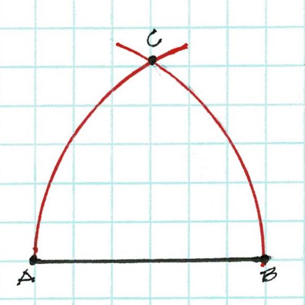
The builder stood where he wanted the main wall of the house to be. He pegged the width he chose with twine A-B. That length became his radius. He drew his arcs to find the center of his circle C.
Then he drew his circle. And found it true. The circle's radius steps off 6 times around its circumference. The arc create the 'daisy wheel'.
A-B in the diagram above became 1-2, the width of the house. The arcs 1-3 and 2-6 of that width crossed at the center of the circle with its 6 points: 1,2,3,4,5,6.
The Lines 1-5 and 2-4 laid out the side walls; 6-3 locate the back wall. Diagonals across the rectangular floor plan proved the layout to be true.
The main block is about 20'x17'. The 2 doors welcomed cooling through breezes in the summer. The wall room on the right may been a later addition to create a parlor, more private and warmer in winter.
Later the builder added the shed. He made his twine the length of the house, folds it in half and then in half again. He then knew what was 1/4 the length of the house (x). He laid out that length (x) 3 times to get the depth of his shed. He stretched his twine diagonally from one corner to the other. If the twine measured5 (x) his shed walls were a 3/4/5 rectangle; the corners 90*, and true to the main house. The shed roof framed cleanly against the house and was weather tight.
The circle and the 3/4/5 triangle - Practical Geometry - were the only measuring systems necessary to construct this house.