Archive - 2022
Tuesday, November 29, 2022
Virginia Folk Housing, Part 2 of an update
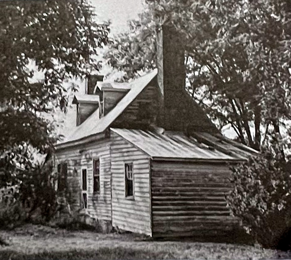
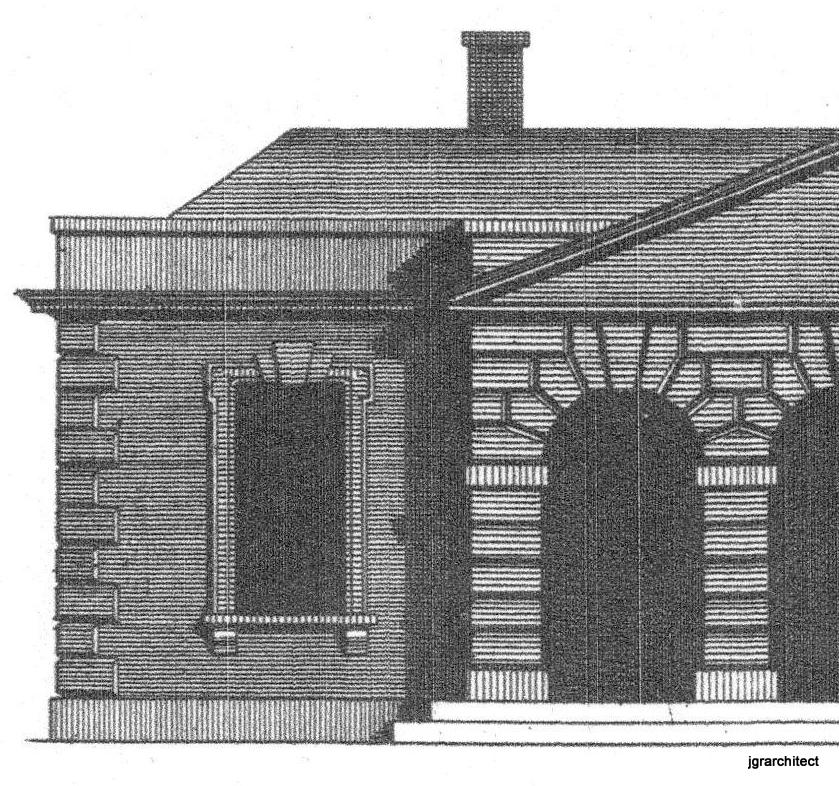
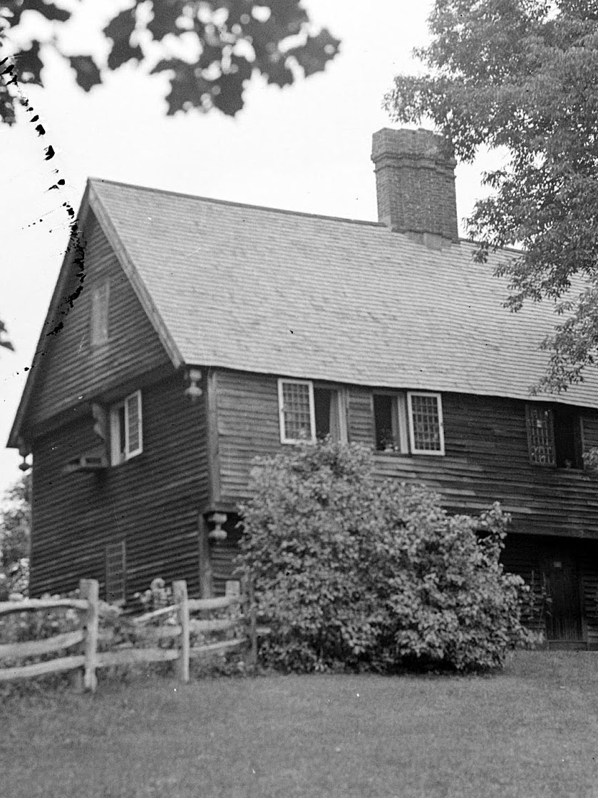
The Moore House* photographed by Henry Glassie, built before 1750.
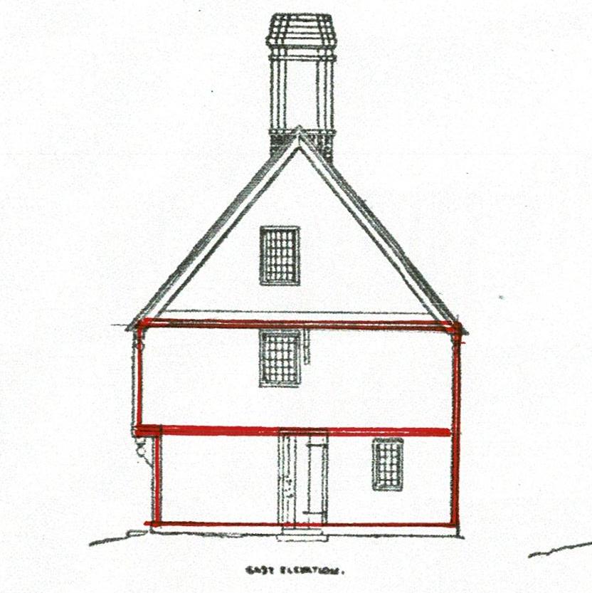
This house has 2 rooms up and down, 2 fire places, 2 chimneys, and a shed on each end. The main block is double the size of the house I wrote about in Part1: https://www.jgrarchitect.com/2022/11/virginia-folk-housing-update.html
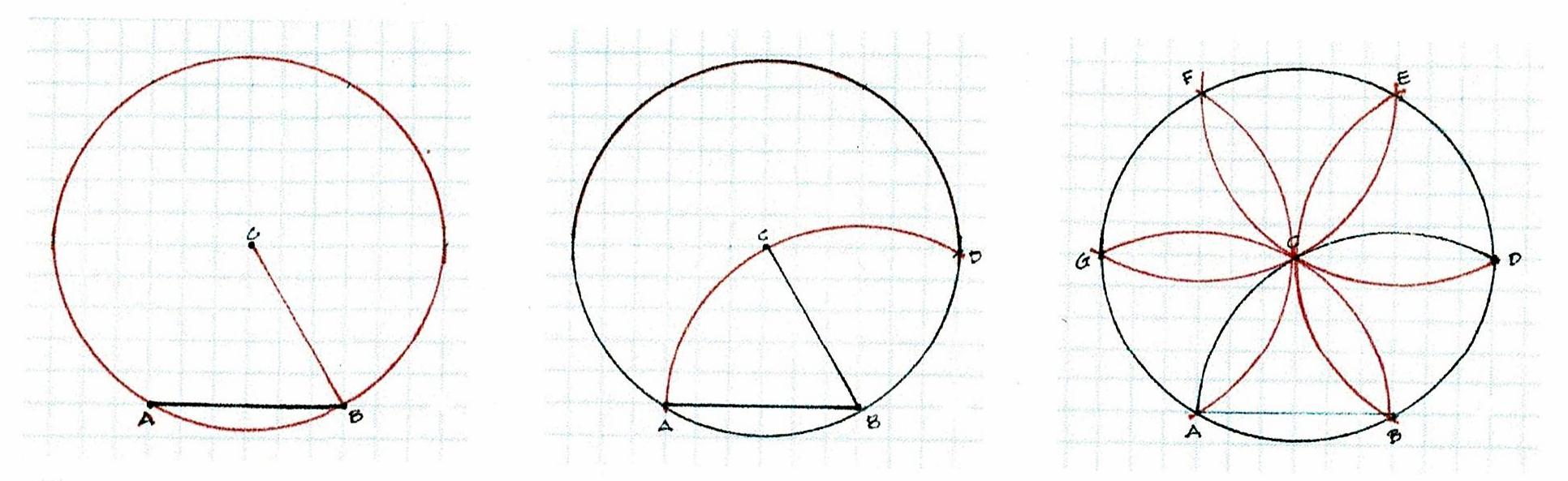
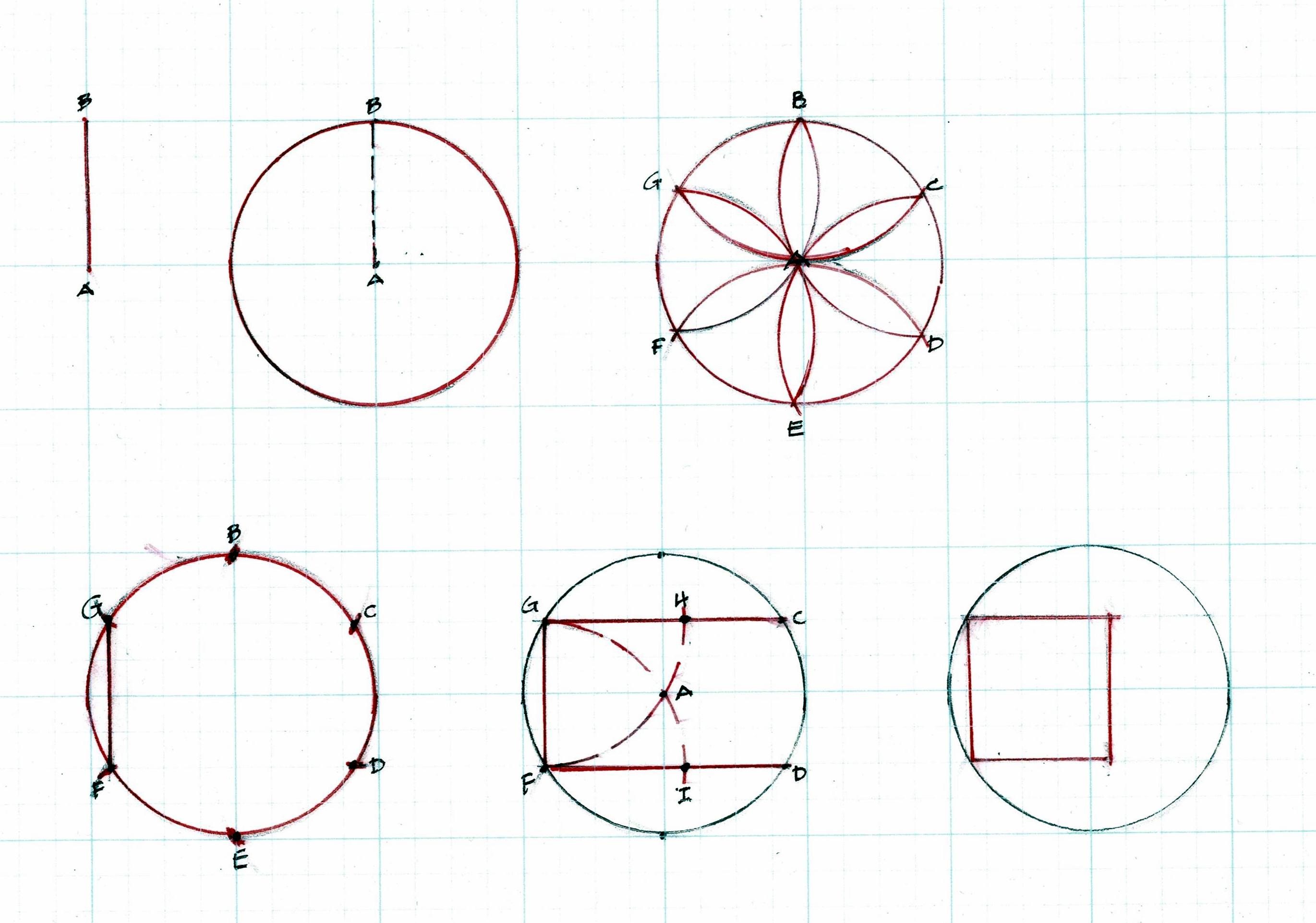
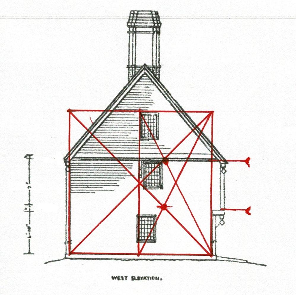
The geometry begins as it did in Part 1, using the width as the circle's radius.
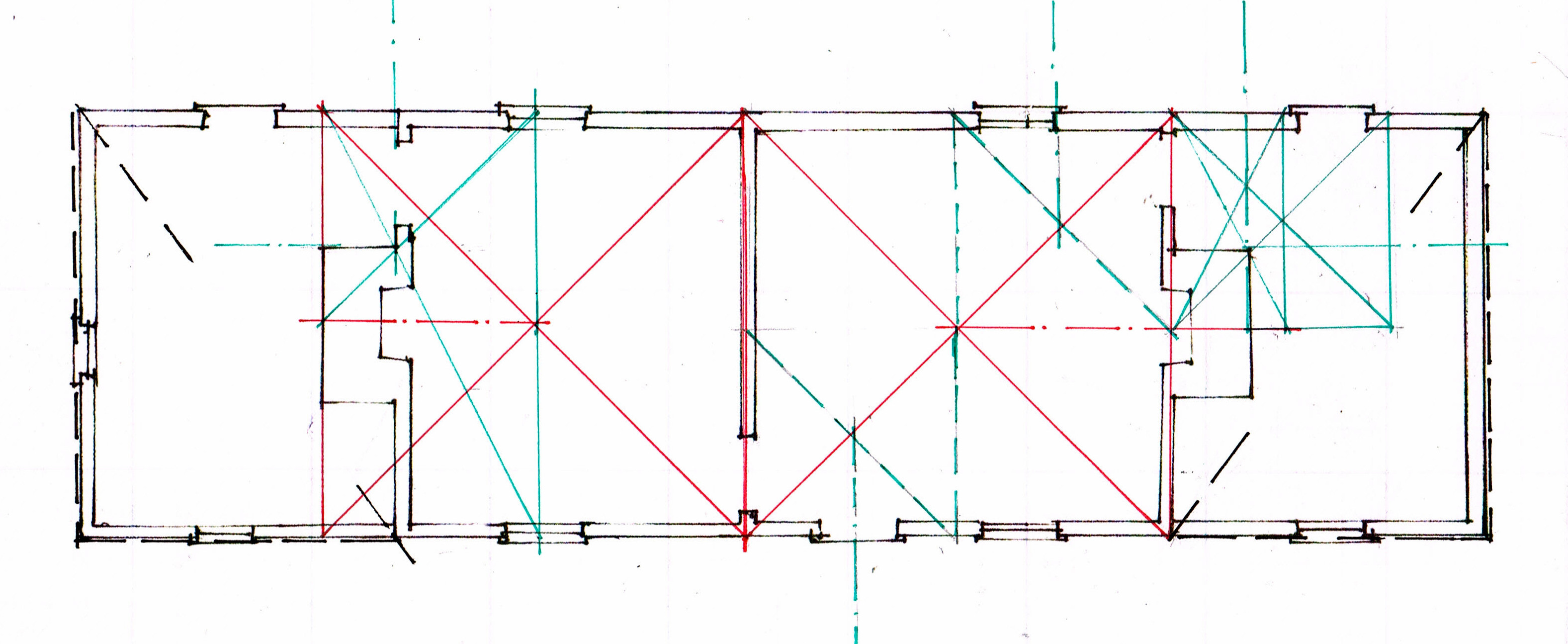
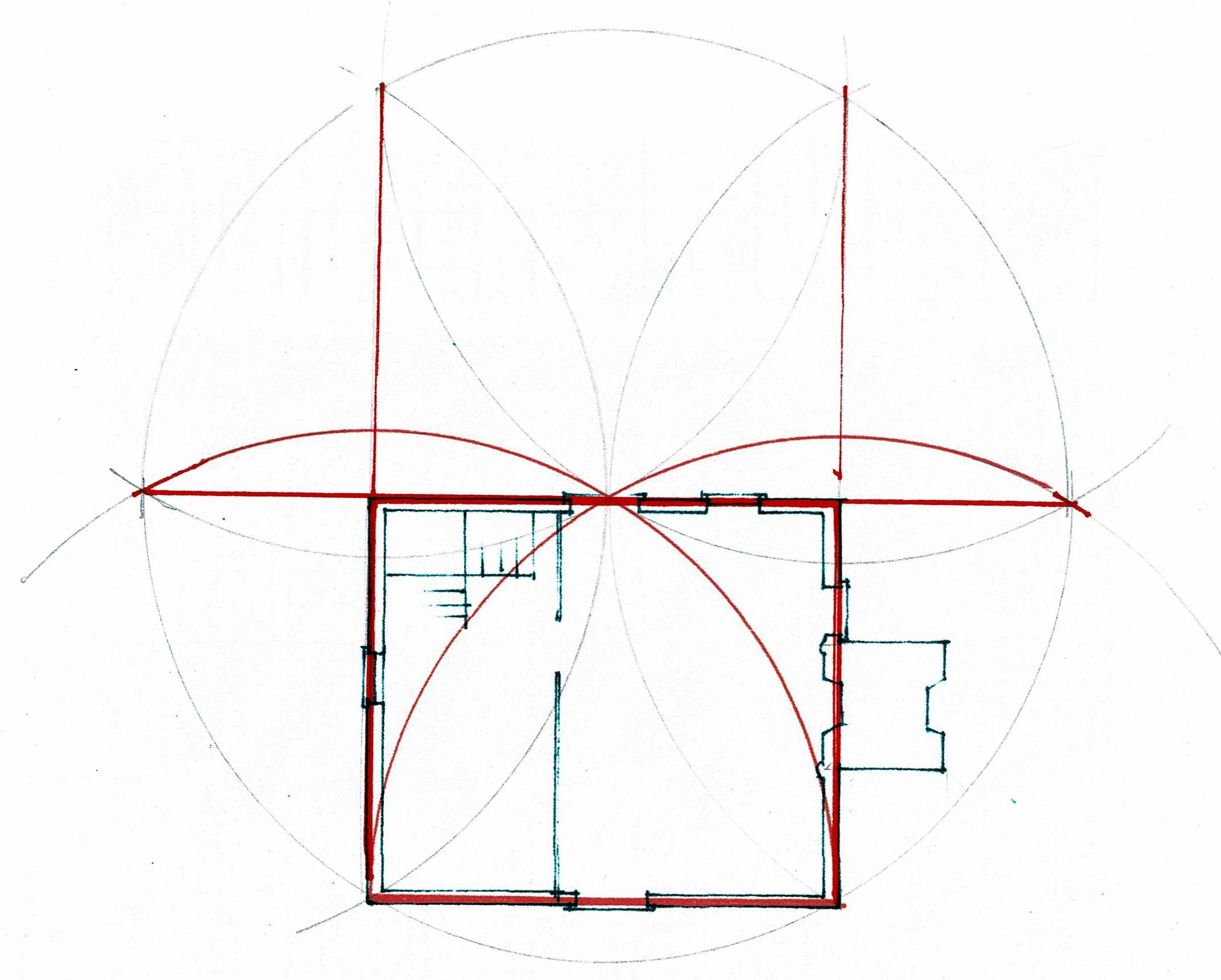
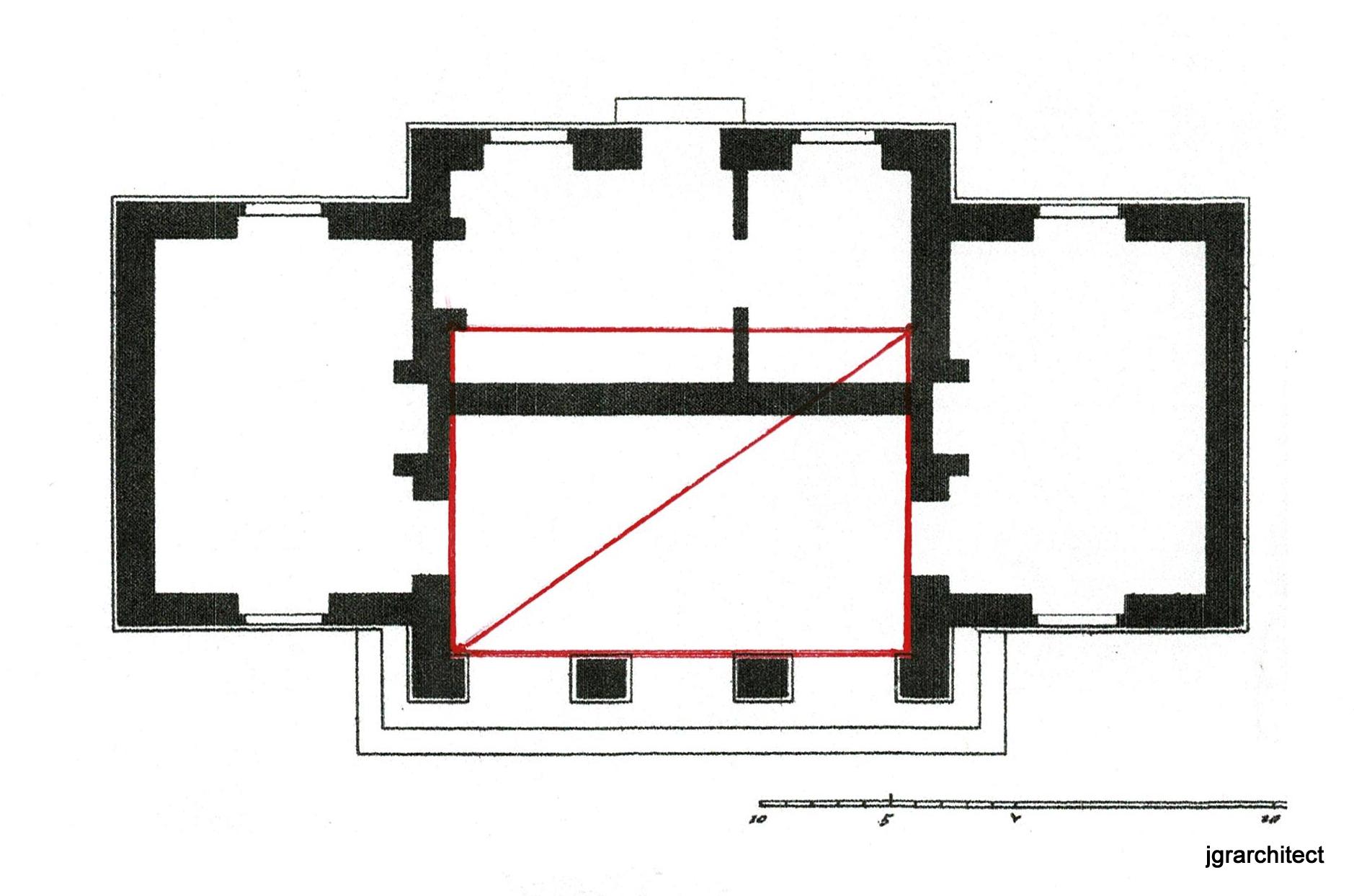
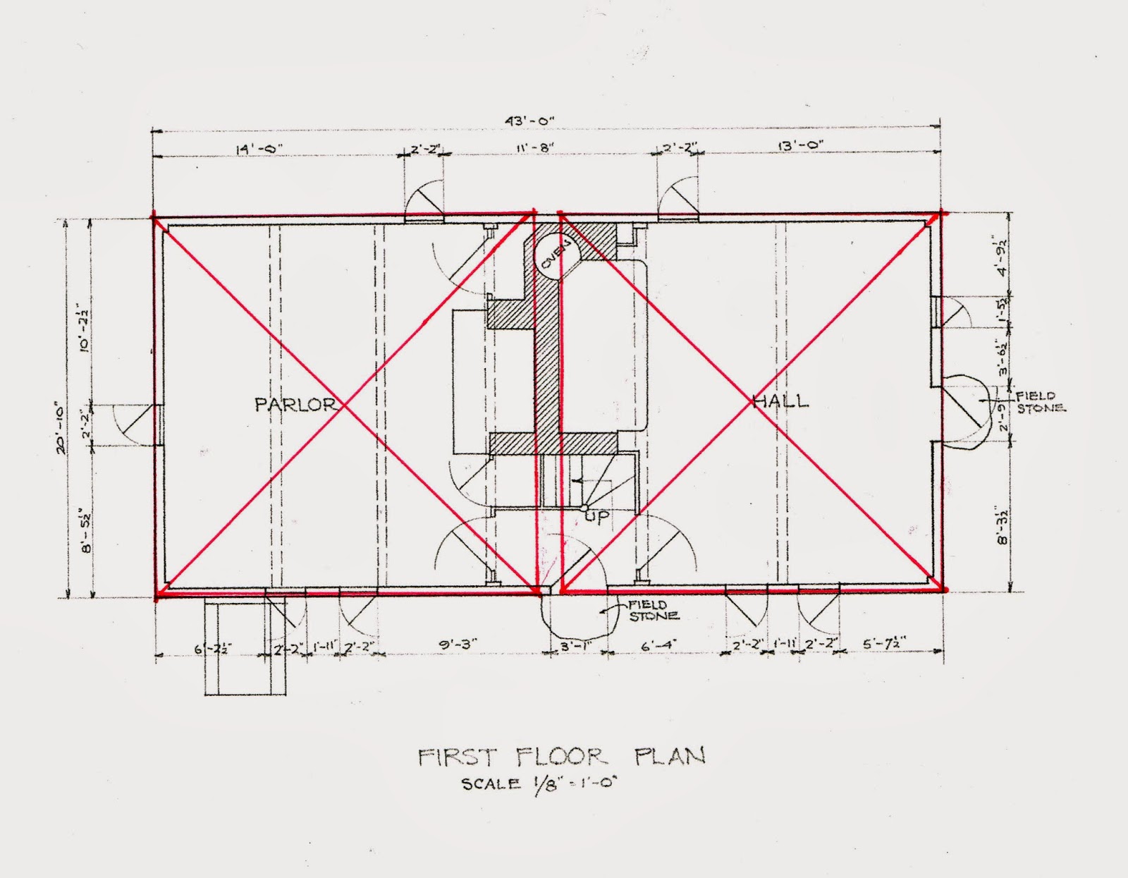
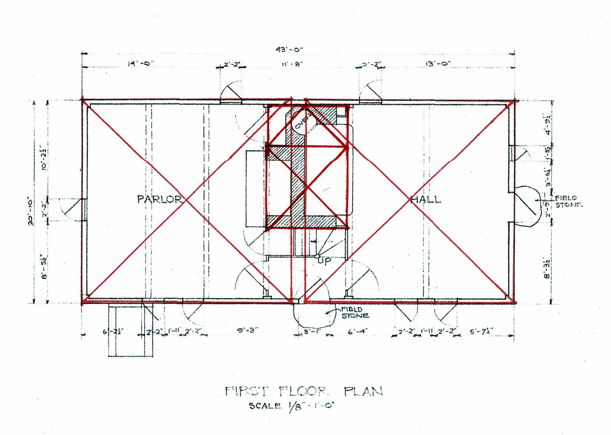
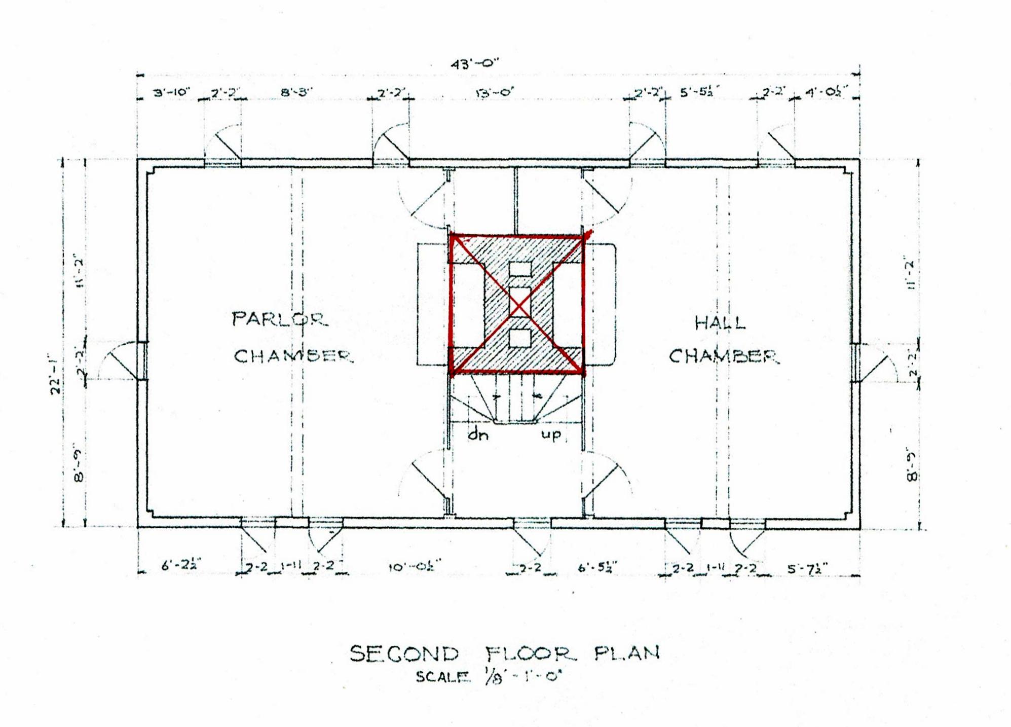
Here is the floor plan: 2 rooms with fireplaces, and sheds on both ends.

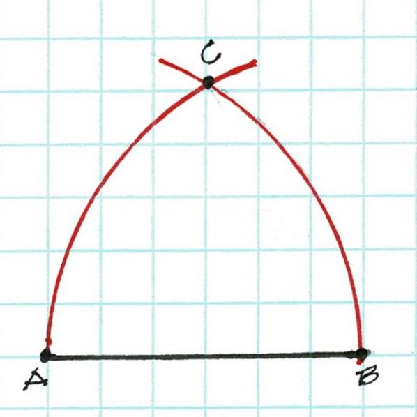
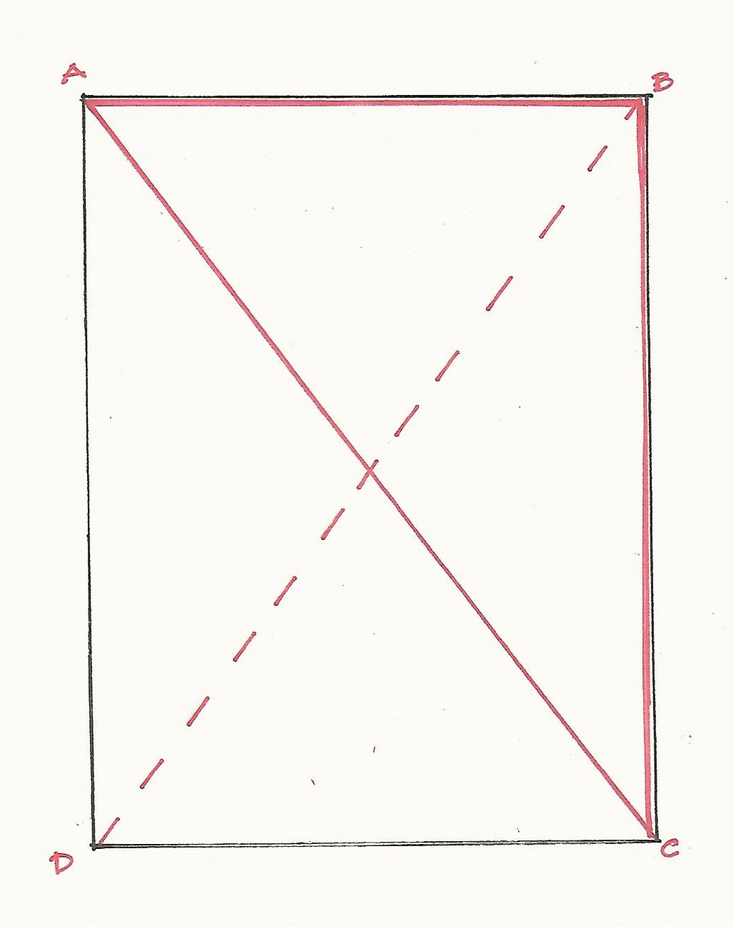
The daisy wheel progression begins with a length A-B which becomes the radius of a circle here lettered C-A.
The daisy wheel for this house begins with the left wall of the main house.The daisy wheel for this house begins with the left wall of the main house.
That wall's width is the radius, 1-6. A is the center of the circle. The daisy wheel lays out the other 4 points, 2, 3, 4, 5.
Lines 1-3 and 6-4 are the sides of the house. 2-5, the diameter of the circle, lays out the interior wall.
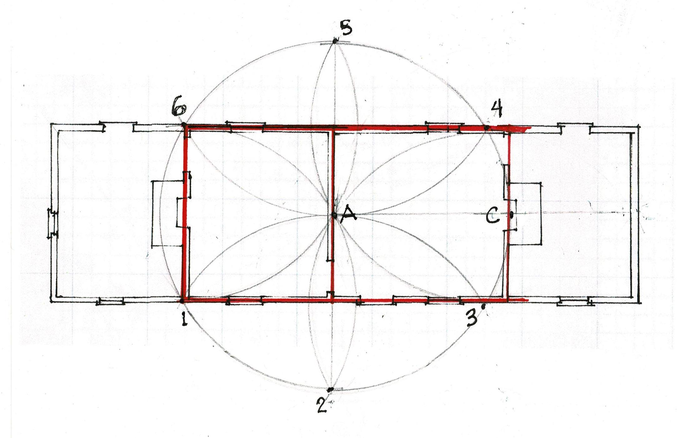
Lines 1-5 and 2-4 can extend forever. Where is the right end wall of the house located? Where is C?
It's at the end of the circle, but that's only a point, not a line. 2 points are necessary to draw a line to mark the right end of his foundation and the floor of the house.
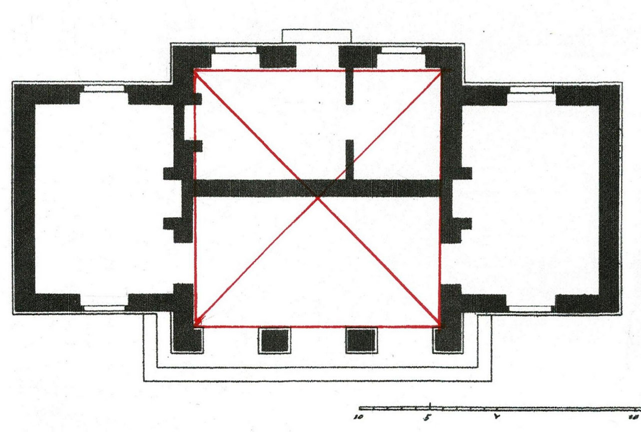
If the carpenter extends his arcs he can quickly find the missing points.
Extend the arc centered at 3 (2-A-4) to B. The arc centered at 4 (5-A-3) crosses the earlier arc at B. He has 2 points: A and B, And can draw line A-B.
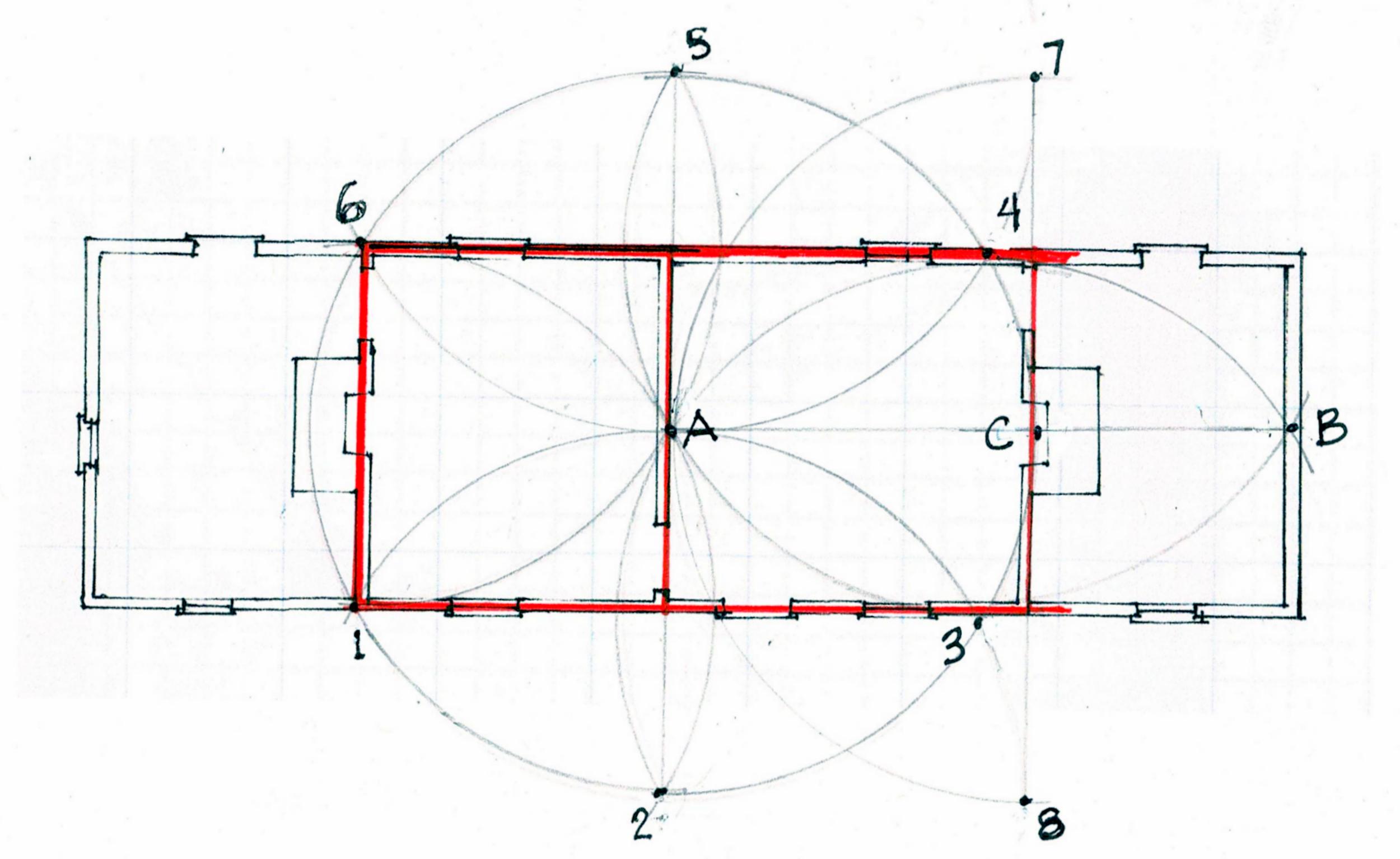
Now C is fixed at the intersection of A-B. C is the center of a new arc, (7-A-8). The extended arc from 5 (6-A) crosses at 7. The arc 2 (1-A) crosses at 8. 7-C-8 locates the right wall.
C also locates the center of the fireplace and the chimney.
The daisy wheel is often dismissed as a design tool. It is flexible, quickly drawn, and accurate.
The geometry comes from the first length - the width chosen by the owner and builder for this house. That width, and the house, could be bigger or smaller to suit the owner's needs and budget, as well as to the lumber available for joists and rafters.
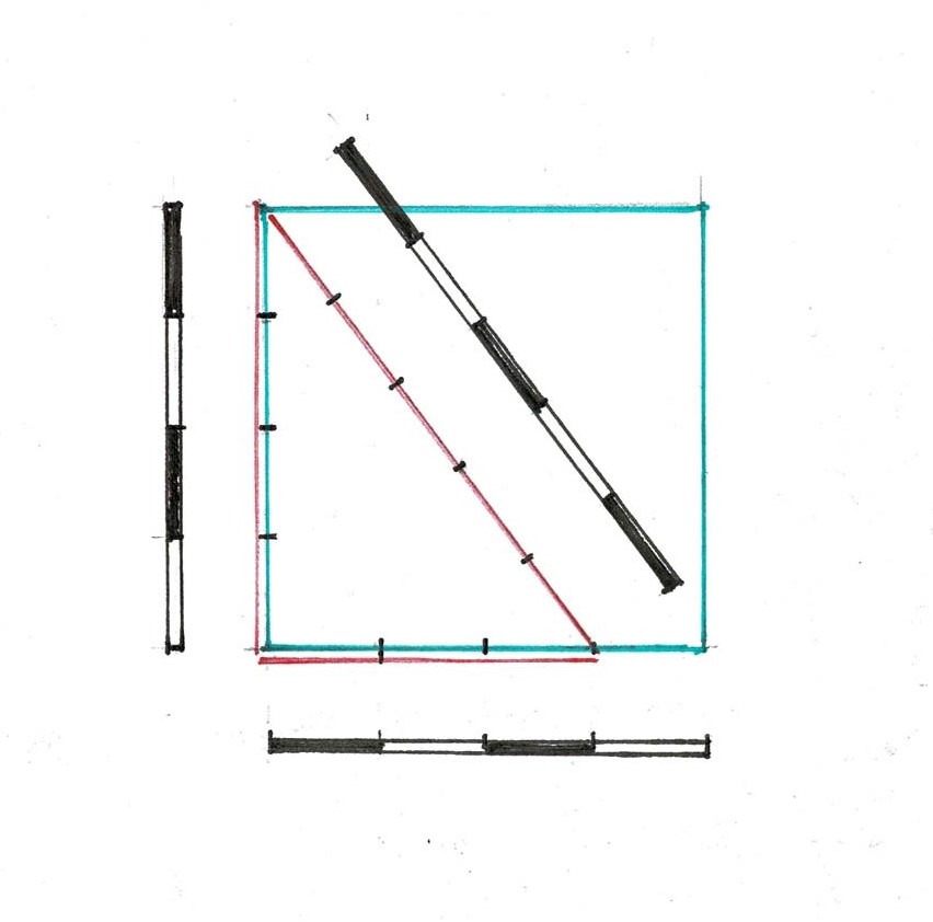
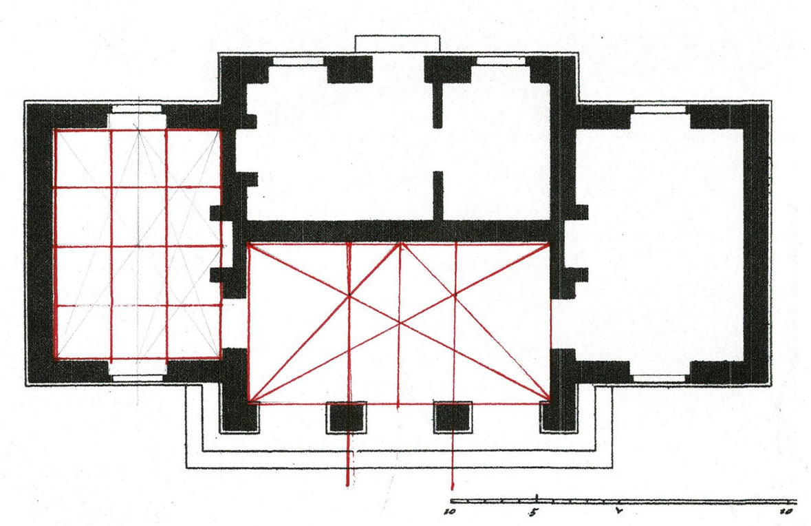
Once the carpenter decides on a width he uses one compass setting, one radius, for the whole layout. Every point is checked. As the lines are marked, the diagonals can prove the layout to be true.
If he drew a layout at a smaller scale, he could easily step off to full-sized construction dimensions with his compass. He could also draw the layout on the ground, stake the points and mark the wall locations with twine just as framers and masons do today.
Consider how the plan would be laid out if the circle is not used. Use a 10' pole - a common tool of the time. Each corner would need to be figured independently; every dimension stepped off separately, and with what accuracy?
The daisy wheel locates all angles and lengths quickly. It has built-in checks from the beginning and as the layout progresses: if the circle doesn't close, the 6 points will be uneven, the arcs won't cross, the diagonals will not match. The layout will not be accurate.
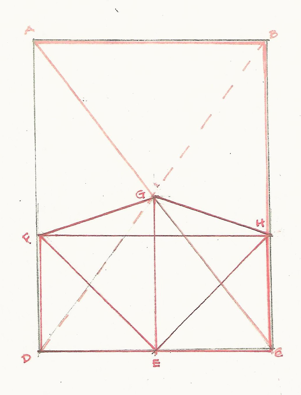
Both wings are 3/4/5 rectangles. See the left shed. The floor plans of wings were usually 3/4/5 rectangles so that they would sit square to the existing house. All the joists would then be the same length; as would be the rafters.

My earlier complex geometry 'works'; the lines are there. But they don't give the basic information the builder needs: the dimensions of the foundation, the floor plan, the size of the house.
*The Moore House, Fig. 31, Type 5, p, 77; the photograph: p.76.
Henry Glassie, Folk Housing in Middle Virginia, U Tennessee Press, 1975; plans, drawings and photographs by Henry Glassie.
Monday, November 14, 2022
Virgina Folk Housing, Part 1 an update
The house recorded by Henry Glassie in Folk Housing in Middle Virginia * were basic shelter for people with few resources. They may have been the first house for someone homesteading, built by a sharecropper or by someone enslaved.
This is Fig. 35, The Parrish House, a "small mid-eighteenth-century house of sawed logs", p. 84 in Glassie's book.*

The geometric diagrams I drew in May 2014,** were accurate but much too complex for these houses. More importantly they didn't begin as a carpenter would: with the size of the foundation and the floor plan.
A carpenter's first question is, " Why?" Then he asks, "How big? How long? How wide?"
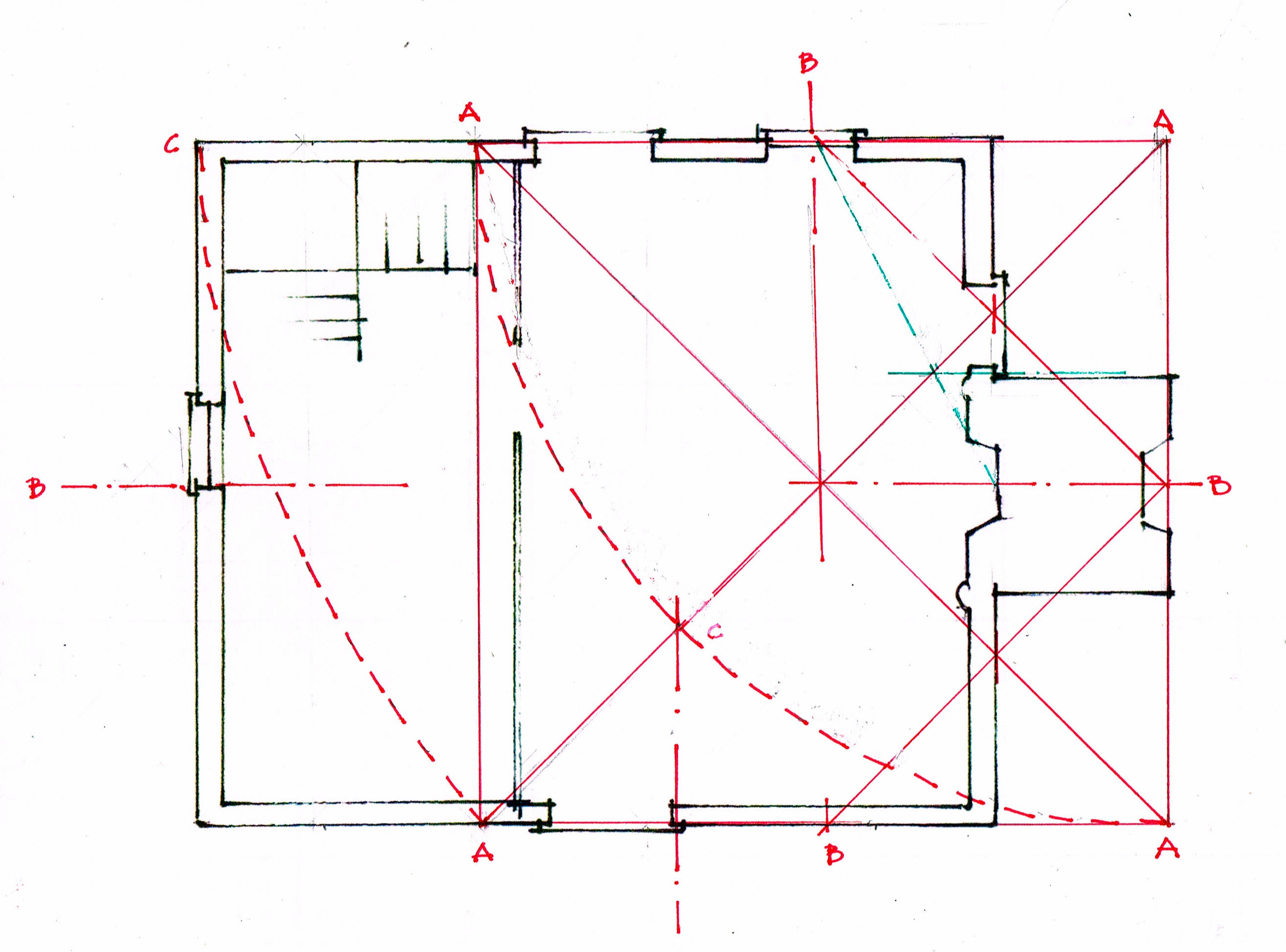
The red line across the bottom of the floor plan is 'how long', about 21 ft. That distance can be the beginning of the layout, the first Line that determines all the others.
That Line can be the radius for a circle:

The arcs of the Line A-B cross at C. That's the center of the circle for the layout of this house.
In the diagrams below: 1) B-C is the radius of the circle. 2) Beginning with B on the circumference the arcs of the daisy wheel are added. The 6 even spaced points around the circle A, B, D, E, F, G are located.

Connect the Lines. A-F and B-E are perpendicular to A-B. G-D is the diameter. They mark the width and length of the rectangle for the house plan. If there is a question about accuracy, diagonals can be used to true the shape.
Here is the plan within its circle, the circle that begins with the carpenter's choice of width, his 'module'.
The masonry block for the 2 chimneys is square, centered, and 1/3 of the width the house. Glassie's photograph shows a shed sheltering that fireplace.
*Henry Glassie, Folk Housing in Middle Virginia, U Tennessee Press, 1975. The book includes more information, drawings, and a photograph of the house. It no longer exists.
** The original post is here: https://www.jgrarchitect.com/2014/04/18th-c-virginian-folk-houses.html. Its companion, here: https://www.jgrarchitect.com/2014/05/18th-c-virginian-folk-houses-part-2.html
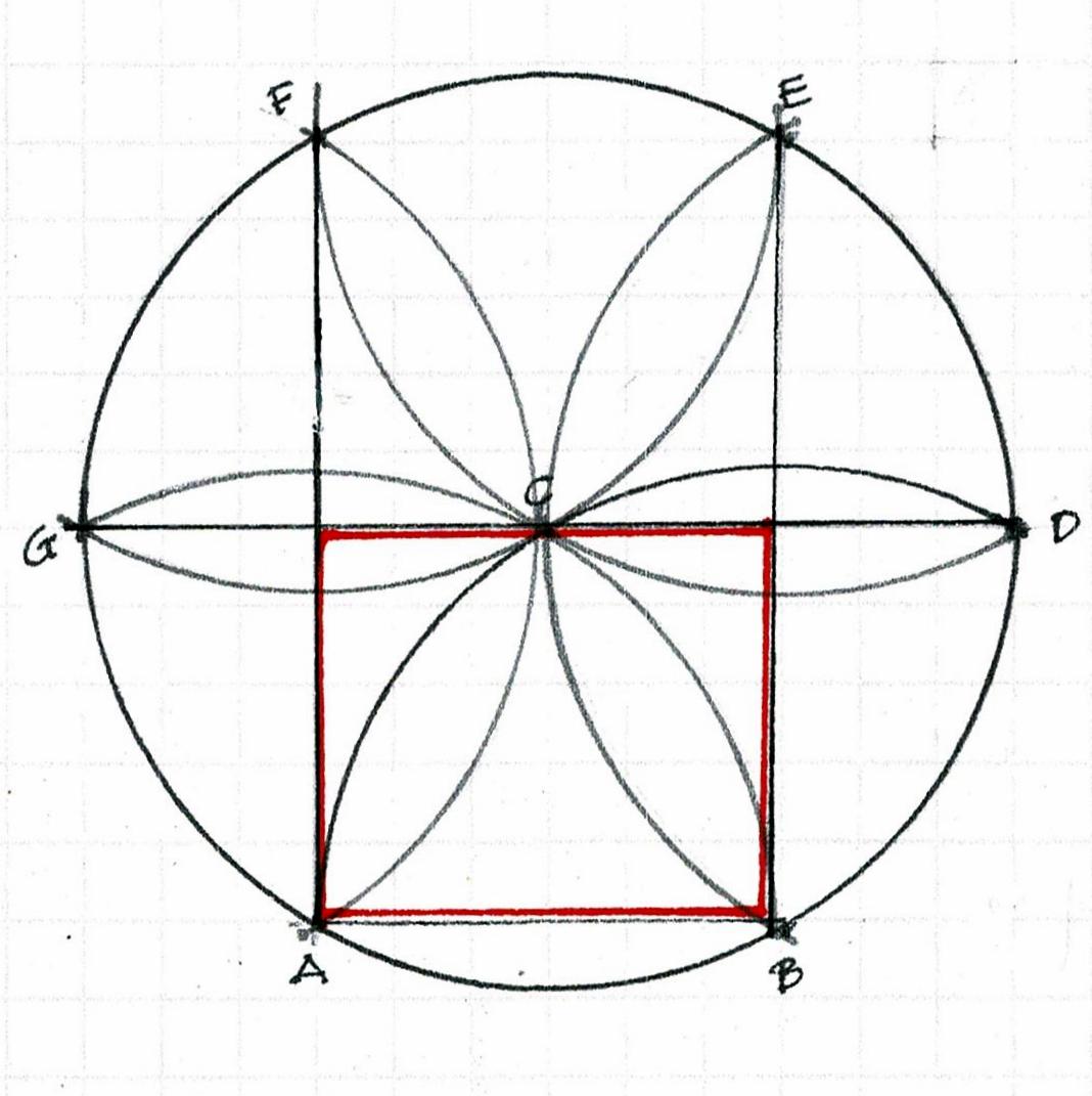
I considered deleting the 2 posts, but their existence brought a comment and question which prompted this update.
Also:
As I read them I realize how much I have learned about geometry since 2014. I saw it and tried to explain it, just as Henry Glassie did in his Rules, Chapter IV, The Architectural Competence.
When I began to study Practical Geometry there were no books, no one for discussions or critiques. I was teaching myself, reading early pattern books line by line. Laurie Smith was the only person I knew who saw geometry as I did, and he was in the UK. Later that year he came to the States; I took a workshop with him. I was able to work with him until his death last year.
I don't want this information to be lost again. I want others to find it, question it, reject and/or improve upon my analysis, their own analysis, expand our understanding.
Wednesday, October 5, 2022
Serlio's Lines
Lines.
That's the word they used. Lines It was an important word, often capitalized.
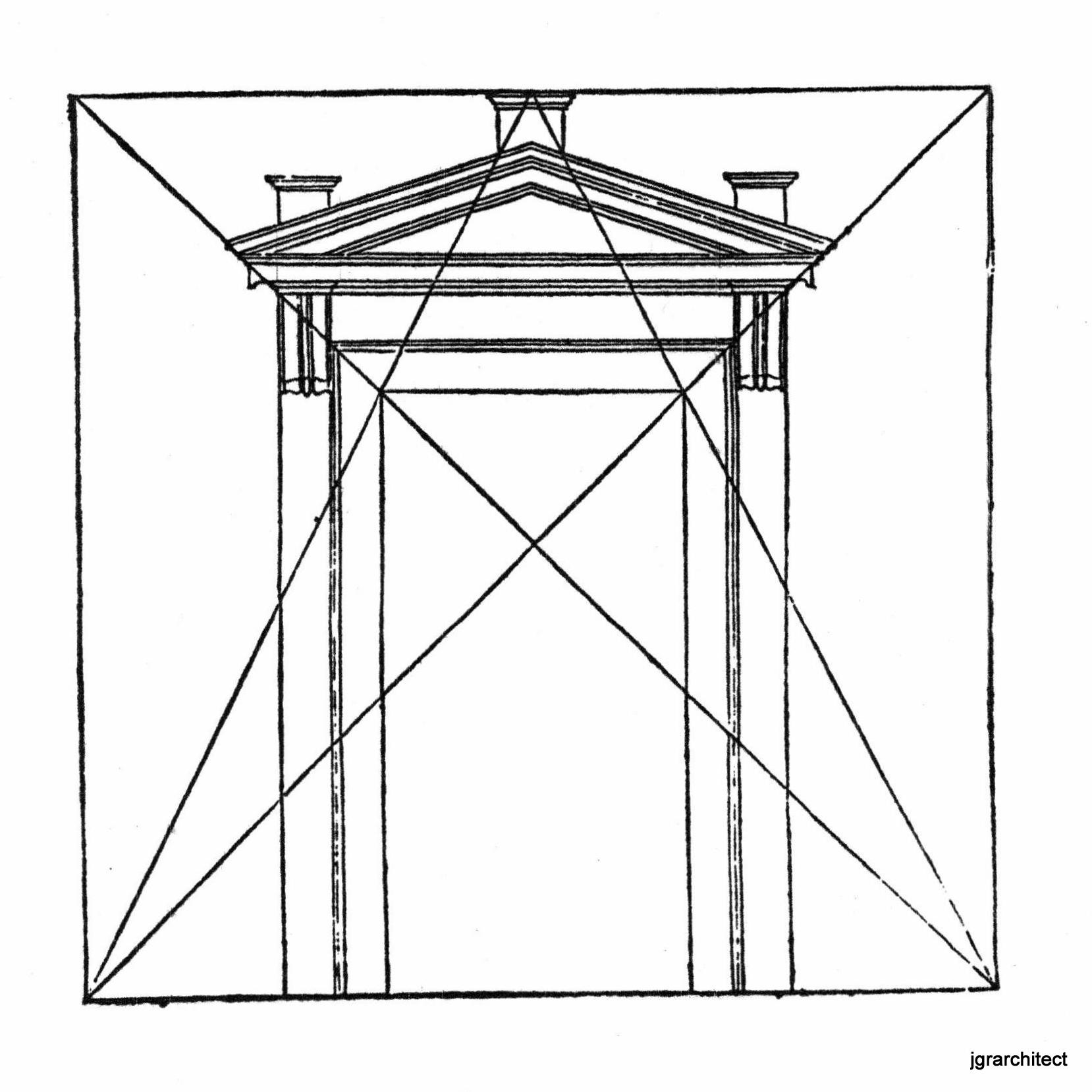
Sebastiano Serlio writes, ".... if the architect wants to build a temple door which is proportional to the place, he should take the width of the central body of the temple, that is the floor space - or between the walls if it is small, and between the pillars if it has transepts. From this width he should draw the same height which will make a perfect square.
... He should draw two diagonal lines and then the two other lines from the bottom corners to the top [center.] The "lines will form the opening of the door, and they will also enable the ornaments to be carved, as is shown... If 3 doors... were to be built in the face of a temple, the same proportions could be used in the smaller sides." *
We use this word: "line". Usually we add helpful adjectives.
Metaphoric lines: "toe the line", "step over the line", life line; or bus and subway lines.
Demarcation lines: fence line, property line, finish line, white line, sight line.
Rope that becomes a line: tow line, clothes line, fishing line, electric line.
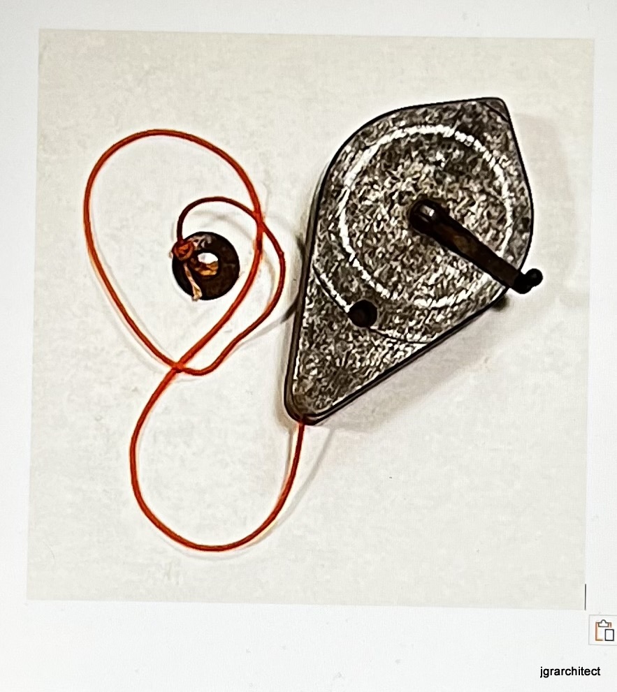
And in construction: chalk line, plumb line.
The line shown here can be either. a chalk line that can be rewound into the case, or a plumb line by hanging the line on a peg and using the case as the plumb bob.
We check that a foundation, a frame is true with matching diagonal lines.
There is also 'straight line', an oxymoron in geometry.
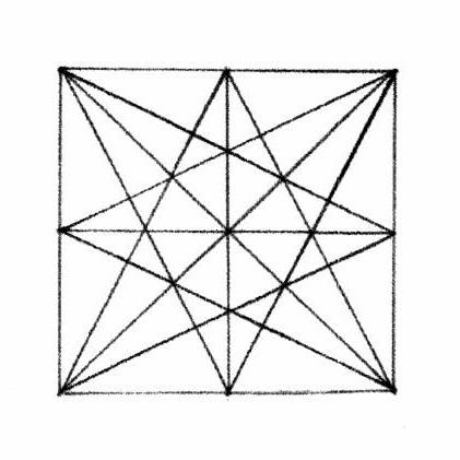
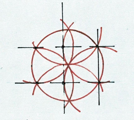
Serlio's definition is geometric; a line is "a straight and continuous representation from one point to another, having length without width." Here is his diagram shown above, rotated and then all 4 diagrams overlaid to make one 'star'.
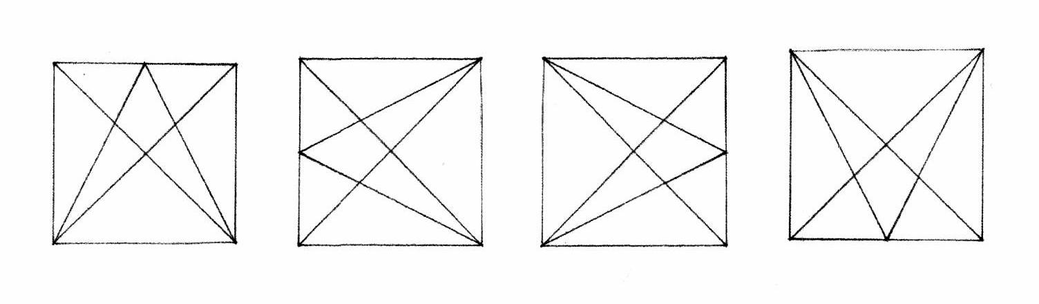
He ends Book I: On Geometry, " However, honest reader, although the things resulting from the various intersections of lines is infinite, to avoid being long-winded I shall come to an end."
Do we, in 2022, know what these words, the various intersections of lines mean? What results from them?
The easiest answer is the lines can divide a rectangle or trapezoid in half, vertically or horizontally, or in 3, 4, 5, 6 (etc.) equal parts.
Any 2 points can establish a line, so lines can create simple or complex patterns.
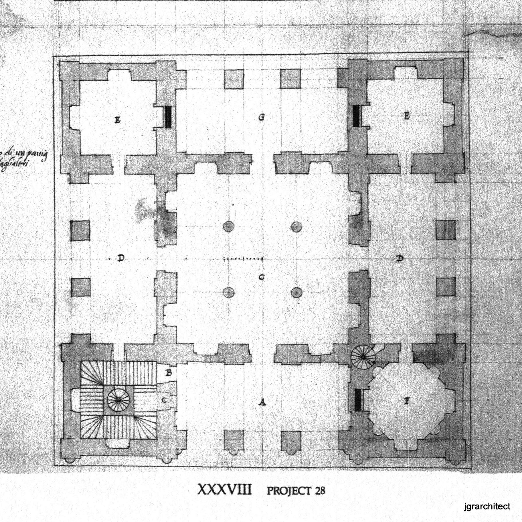
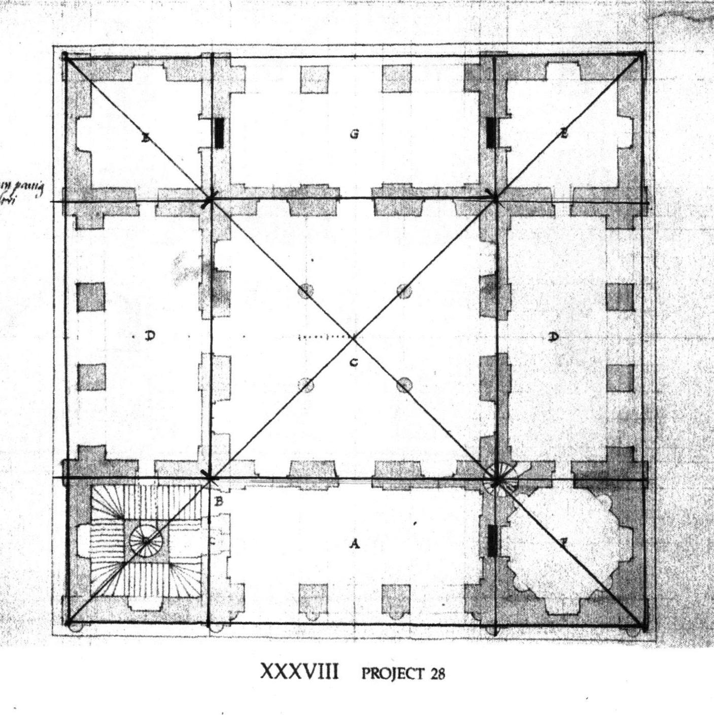
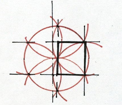
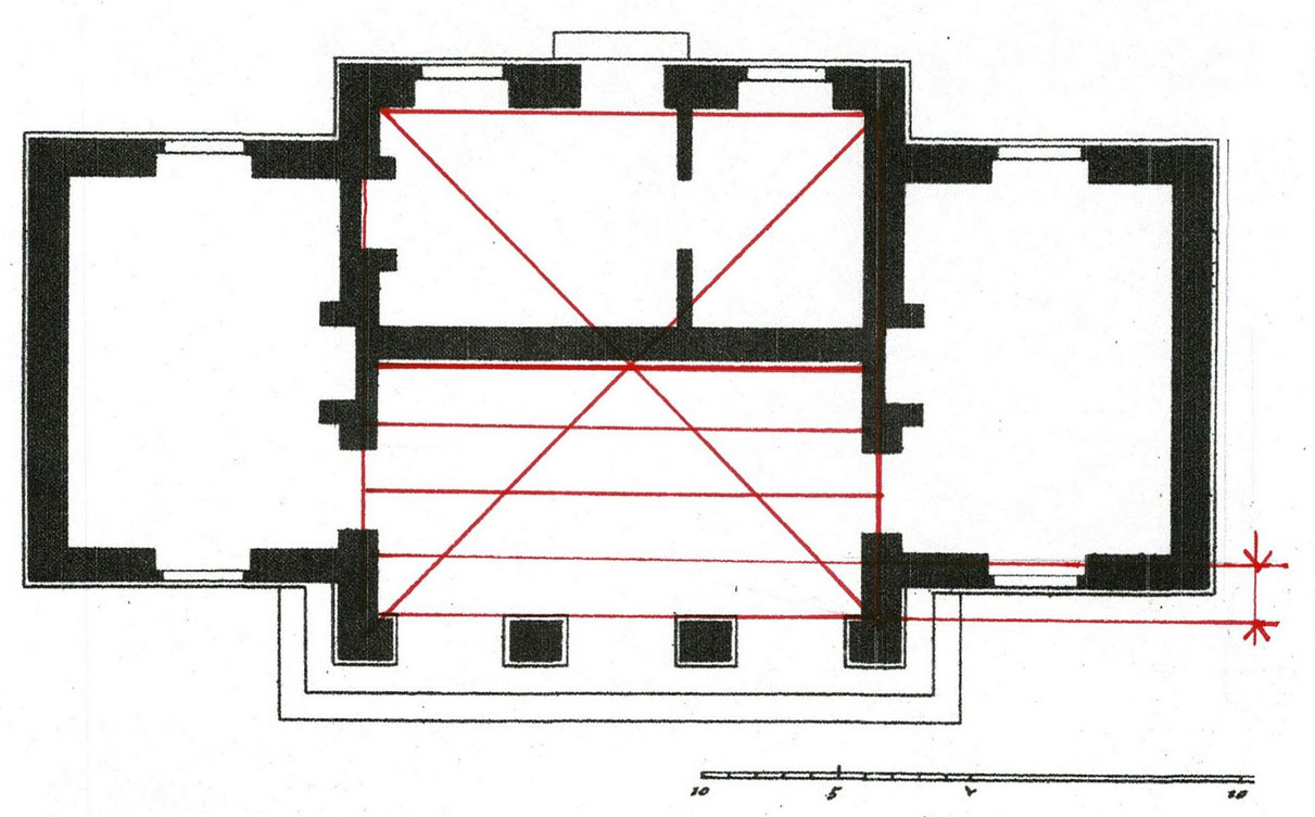
Here is one of Serlio's designs that begins with a square and its diagonals. Every dimension on the plan comes from that initial diagram.
This villa comes from Serlio's Book VI: On Geometry, titled: Treatise: On Domestic Architecture, written c. 1545-9, Plate XXXVIII, Project 28, of 73 plates.
Serlio drew in the lines for his readers.They were not laid out first. The lines come from the geometry. The placement of columns, walls, openings come from the "various intersections of lines".
He also gives dimensions: those little hatch marks in the center.
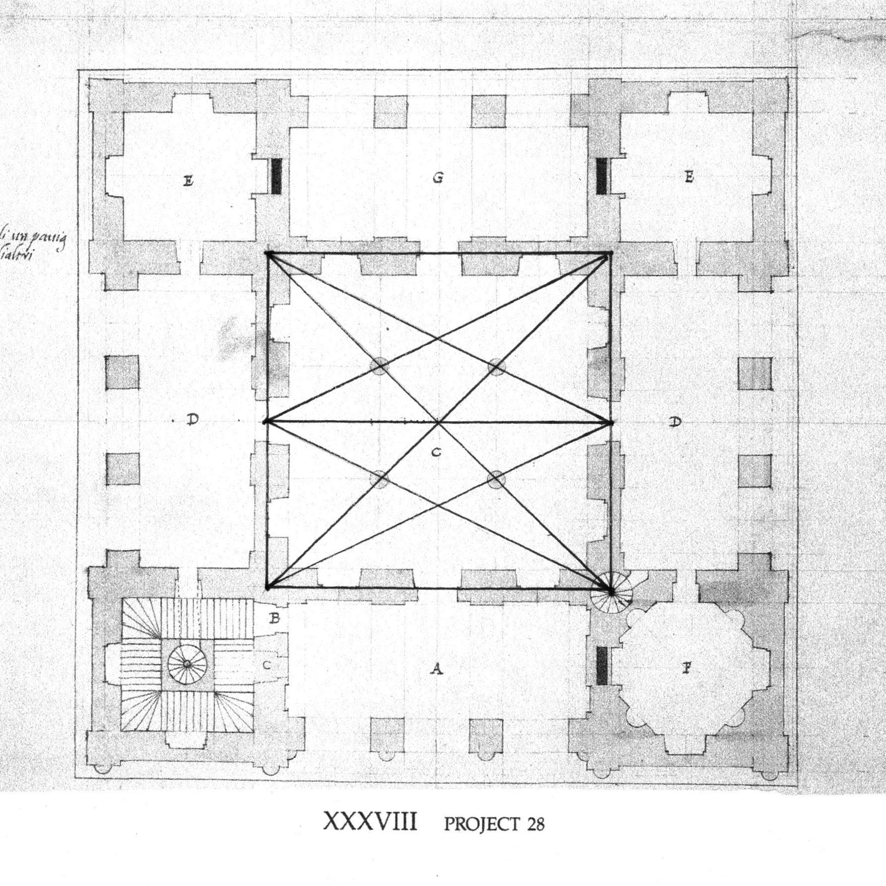
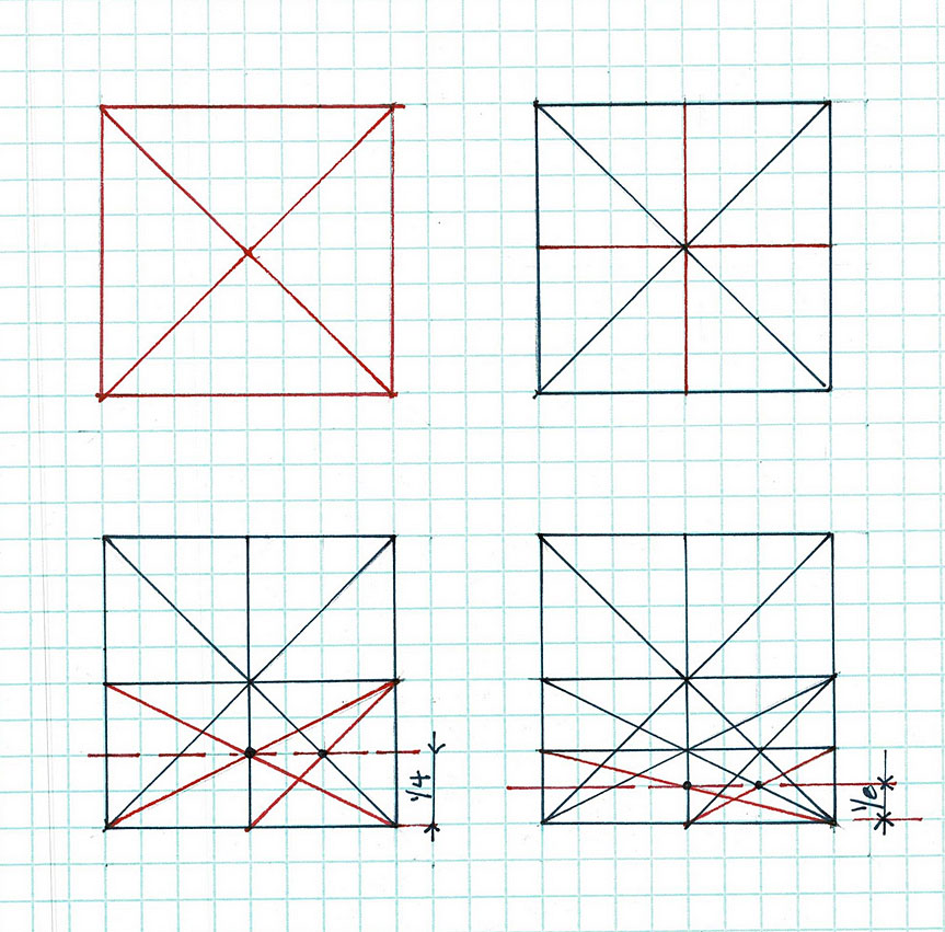
Here's the geometry:
The plan is a square. It is divided into 4 parts horizontally and vertically - 16 equal squares. the top row is: 1 square, 2 squares, 1 square. The bottom row matches it. The vertical rows also repeat the pattern: square, double square, square. The center space is 'left over' - 2 squares x 2 squares. That space is divided into 9 equal squares. The columns mark the intersections.
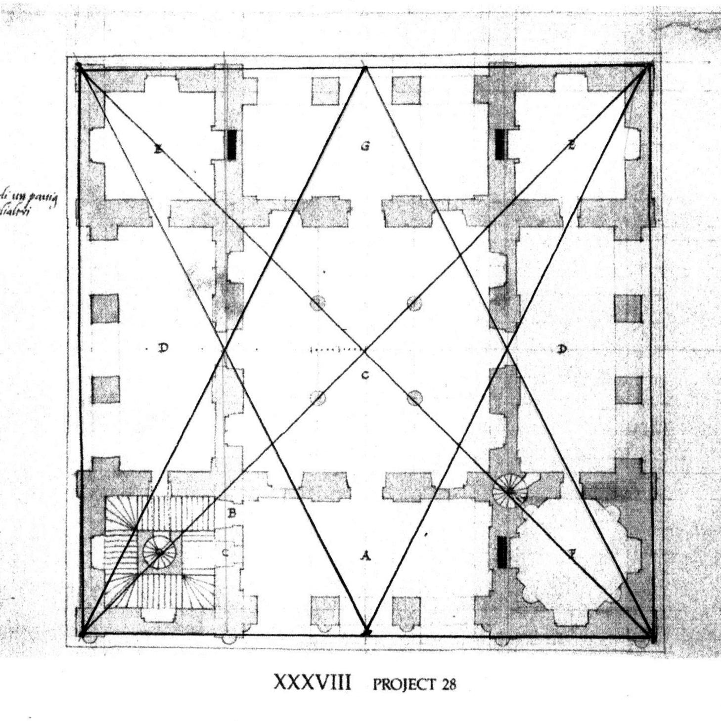
All of this can be easily laid out with Lines. The diagonals neatly cross the corners of the structure and the 4 columns in the central room.
The Lines Serlio used (shown above) to locate the door can also be laid out here. They cross at the center of the walls.
Serlio drew the lines that show the widths of walls, openings, and columns. How did he knows where those lines should be? I followed his lead.
His design is a square: I drew squares. I located the center of each side of the plan and added the Lines from center point to center point. This divided the plan into 4 smaller squares. Now there were 4 points of intersection, plus the one in the center.
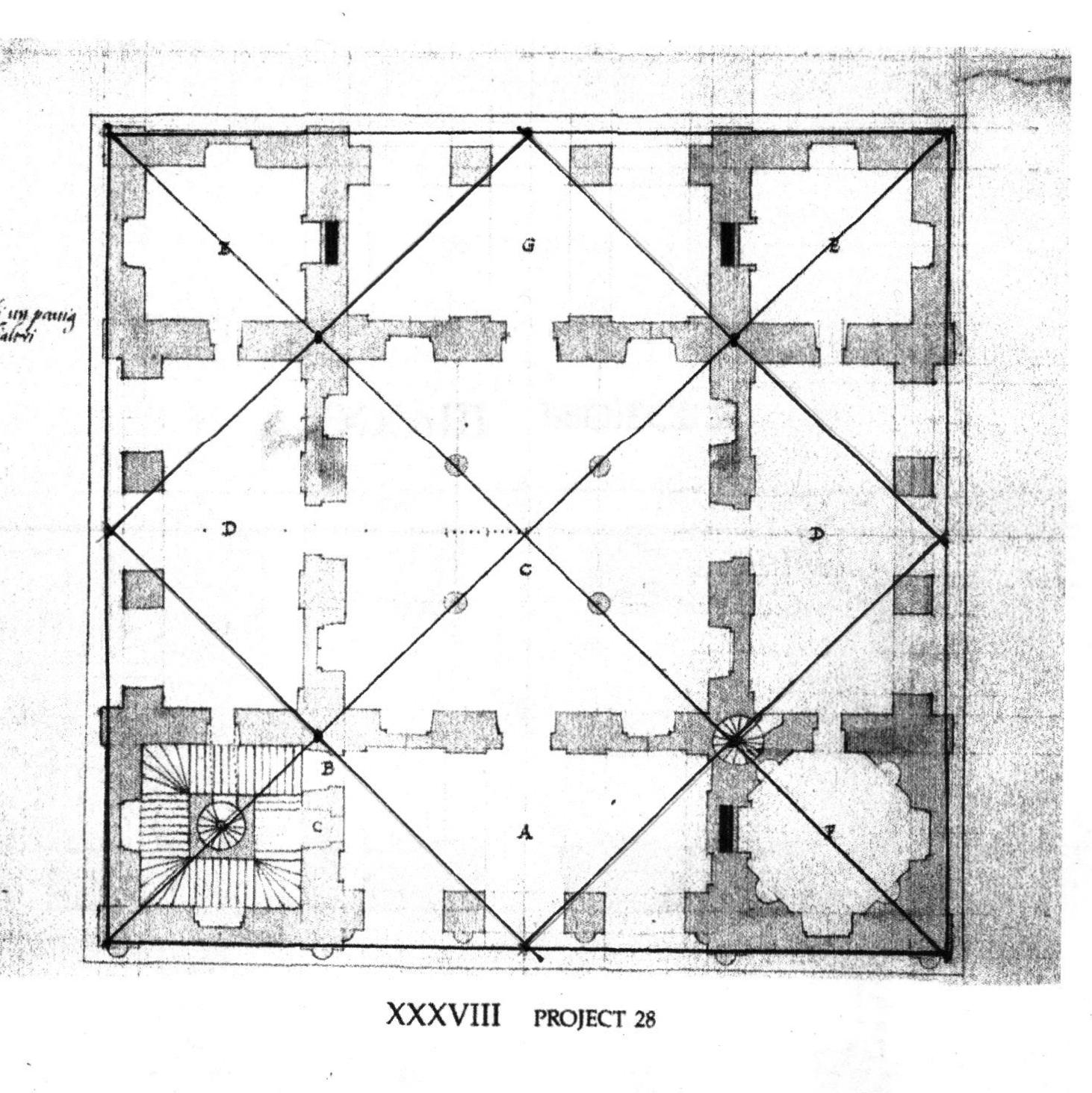
These points allowed more Lines to be added.
The Lines laid out the wall locations. They are at the back of the niches and the fireplaces. They told the mason where to begin his work. He could add the decorative niches, pilasters and mantles in front of the structure. The fireplace flues would line up.
Don't miss the wonderful details: the circular stair - lower left - is at an intersection. The main stair fits neatly into the lower left square, the octagon room in the lower right.
So, the columns?
The Lines - the diagonals that Serlio used in his drawing for locating the door - locate the columns. They are on the 'third points' in the space: dividing the center hall into 9 squares.
This is a simplified version of the star I drew above. It is the 'Rule of Thirds' that we use when we compose images on our cell phones, that artists consider when they compose a painting.
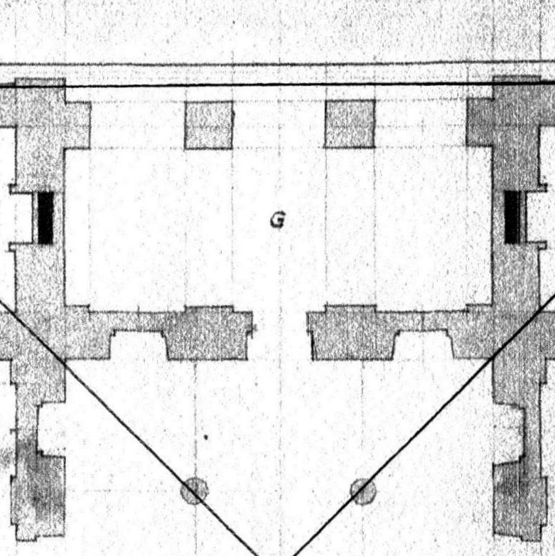
Here is a detail showing how the Lines of the column locations are extended into the loggia 'G'. The Lines determine the placement of the outer side of the square columns. The center space - where G is on the center of 5 Lines - is divided into 4 spaces, easily done using the star. 2 of the spaces equal the opening between the columns, 1 is the width of the columns. Note that the width of the columns is also the width of the walls.
Each dimension comes directly from the first geometry, the square and its diagonals.
The Front Elevation!
That simple layout creates the structure of the villa. Visually the walls became a backdrop for columns, arches, niches, friezes, lintels, dormers, balconies. However it is the geometry which holds all those pieces together.
Note that those square columns, here on the front of the house, have round pilasters added to their front sides, with doubled pilasters on the corners. And don't miss the chimneys!

* Sebastiano Serlio, Book I: On Geometry,
See my bibliography:
https://www.jgrarchitect.com/2019/06/bibliography-includiung-websites.html
Monday, September 26, 2022
The Geometry of Ionic volutes, as drawn by those who used them
Ionic volutes, those curly ends of Ionic capitals, with these wonderful curves!
How were they drawn?
This post began as an exploration of the use of practical geometry vs. the use of the golden section in construction. In all my research I found no references to the golden section as a construction tool.
So, what to do with the images and descriptions I found?
Write about them!
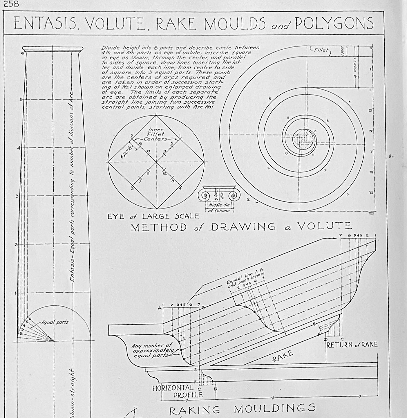
Here are the instructions, written by the designers, master builders, architects, and those who used these volutes.
First, of course, is Vitruvius. He writes, in the 1st c. BCE, "As for the drawings of volutes so they are properly coiled with the use of a compass, and the way they are drawn, the form and the principal of these will be set down at the end of the book.' *
Unfortunately, those drawings at the end of his book are lost.
Beginning about 1540, many architects, builders, historians, professional and amateur, measured the Ionic volutes still extant, those created during the Greek and Roman empires.
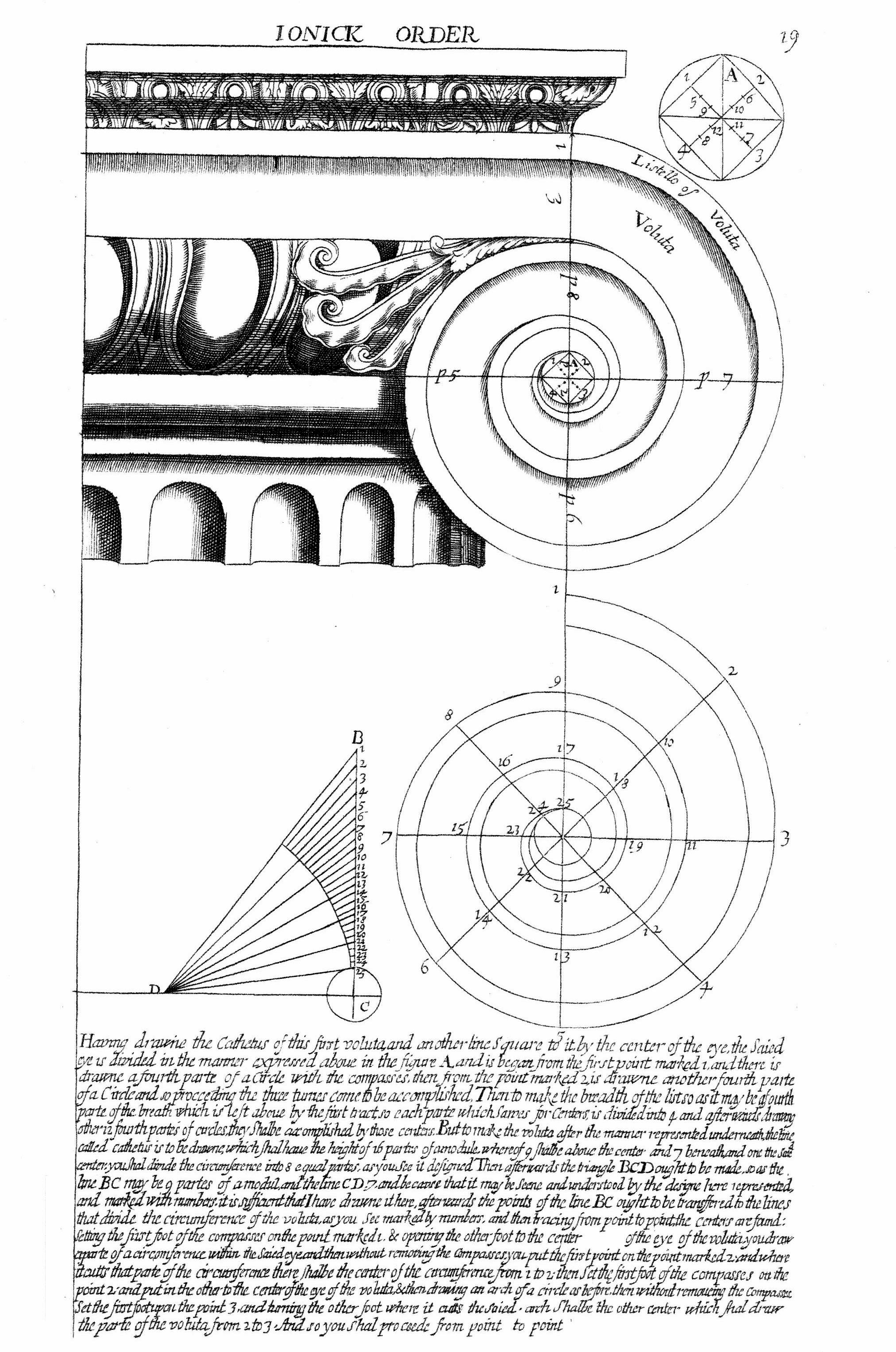
Giacomo Barozzi de la Vignola published his engravings in 1562. The illustration is from the English translation of Vignola by John Leeke in 1669. Vignola begins by noting the reference lines and then the small square in the circle in the upper right corner of the page, 'A'. "Having drawn the Cathetus (the vertical guideline) of this first voluta and the other line S square to it, the said eye is divided in the manner expressed above in the figure A..." 17 lines, total, all quite easy to follow.
Andrea Palladio and Sebastiano Serlio worked at the same time as Vignola and probably knew him.
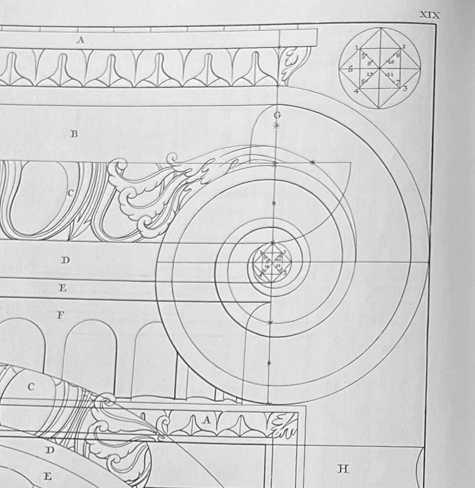
Here is Palladio's drawing in his 4 Books of Architecture, First Book, Plate IXX, 1570.
Serlio's On Architecture, was written before 1550. Serlio takes 32 lines to explain how to draw the volute. He includes, "This matter (as I said) consists more in the practice than in the art because making it diminish both to a greater or lesser extent is dependent on the architect's judgement in placing the point of the compass a little higher or a little lower. The size of the band should not always be all the same."
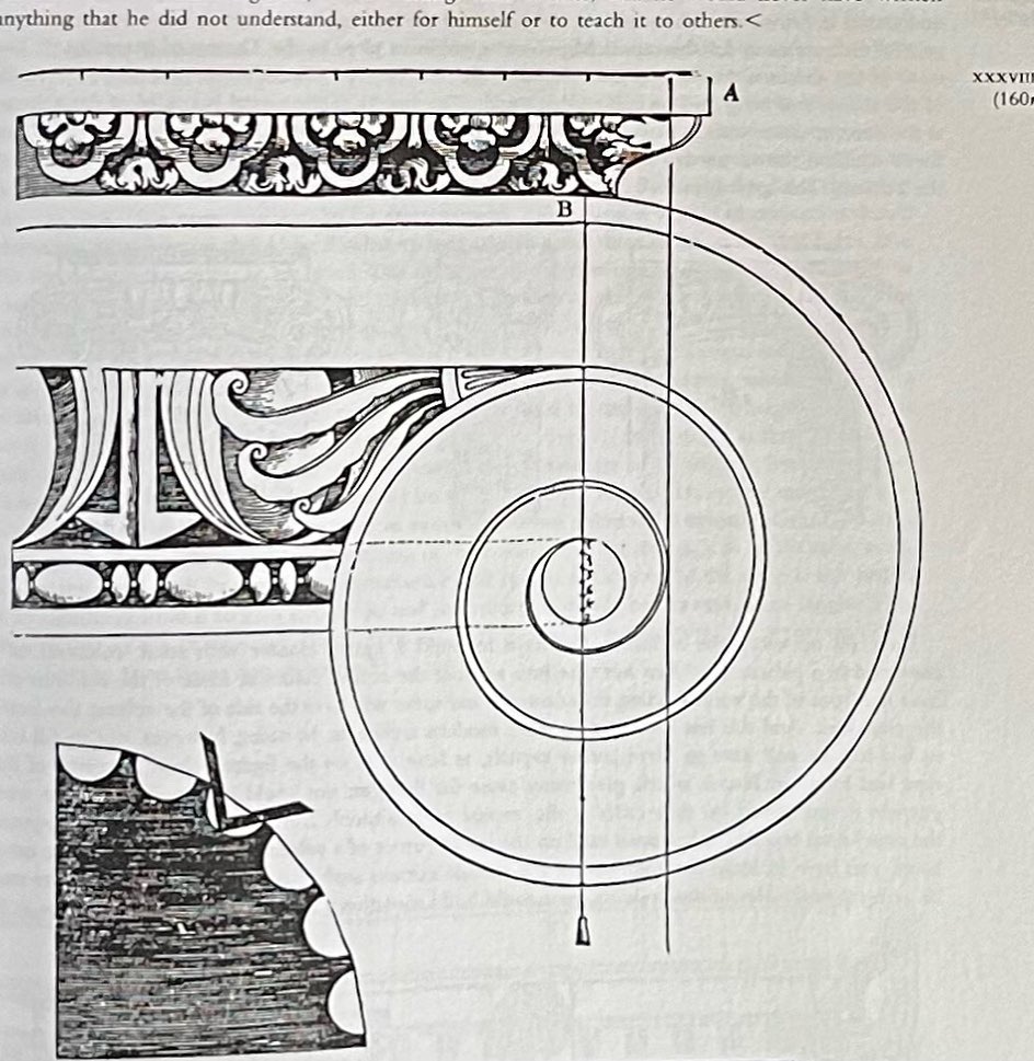
If you look carefully at Vignola, Palladio and Serlio's drawings, you will see that they do not quite agree about the location of those 2 first lines, the cathetus and its perpendicular. They probably had measured different volutes. Later writers mention which volutes they think to be most perfect.
Serlio's treatise was translated from Italian to Dutch to English in 1611. A complete English translation of Palladio wasn't available until after 1715.
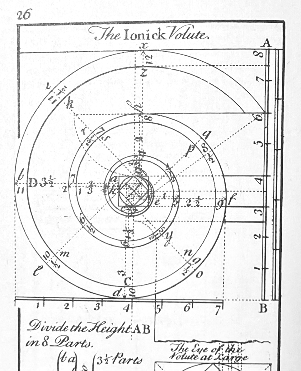
Batty Langely's The Builder's Director or Bench-Mate, was published in 1745, London, a compilation of "all that is useful to Workmen,... and at so easy a Rate, as to be purchased by any common Labourer." He includes variations for Ionic capitals: 'modern' and 'ancient' all of which are explained by 'Minutes and Parts'. This is his first drawing of 6.
Batty Langley's books continued to be published after his death in 1751, and were available in the Colonies.
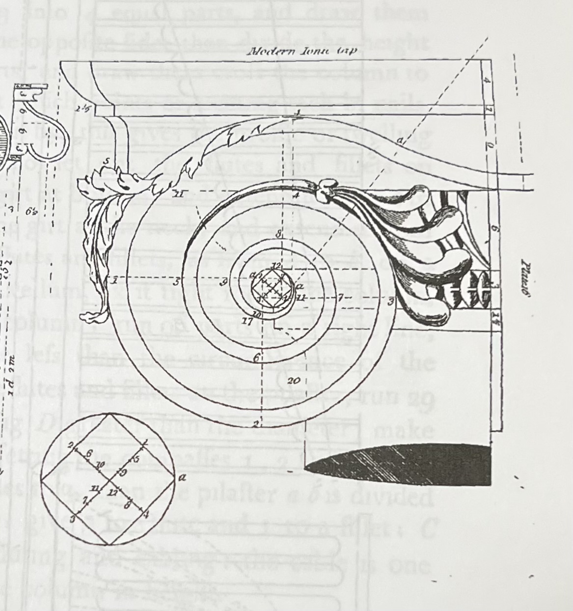
William Pain published similar 'practical builder' pattern books at about the same time. Here is his Plate XVI from The Practical House Carpenter, or Youth's Instruction, London, 1794, for volutes with parts. He writes that he has included " ... all the measures figured for practice: to draw it, set the compasses at the angle a in the profile..." He rewrites the earlier instructions given by others and reminds the reader again that he has included "the measures all figured for practice."
Owen Biddle's pattern book, The Young Carpenter's Assistant, 1805, Philadelphia, includes these less flowerly drawings and instructions.

Asher Benjamin's American Builder's Companion, originally published in 1804, includes similar diagrams.
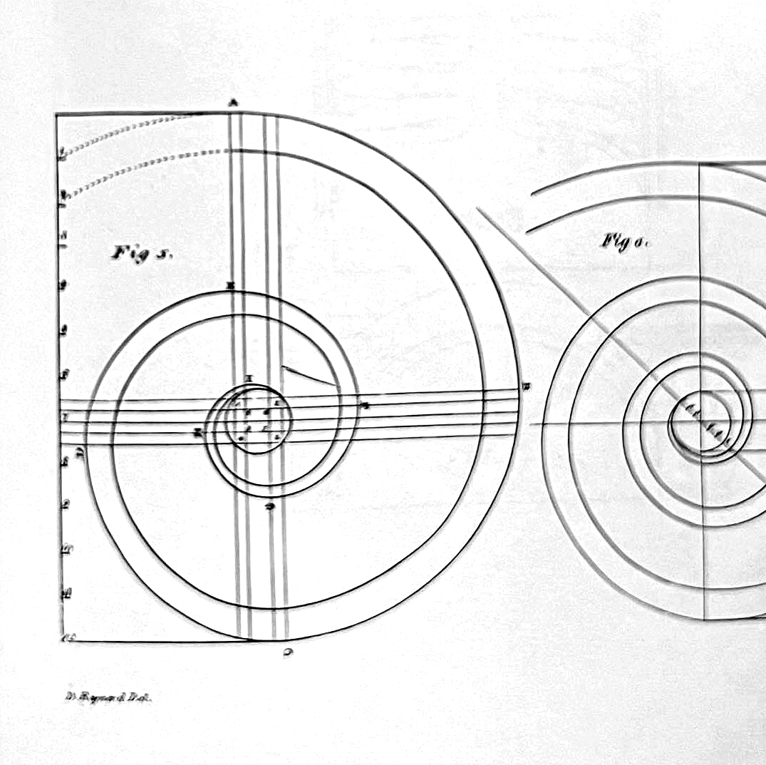
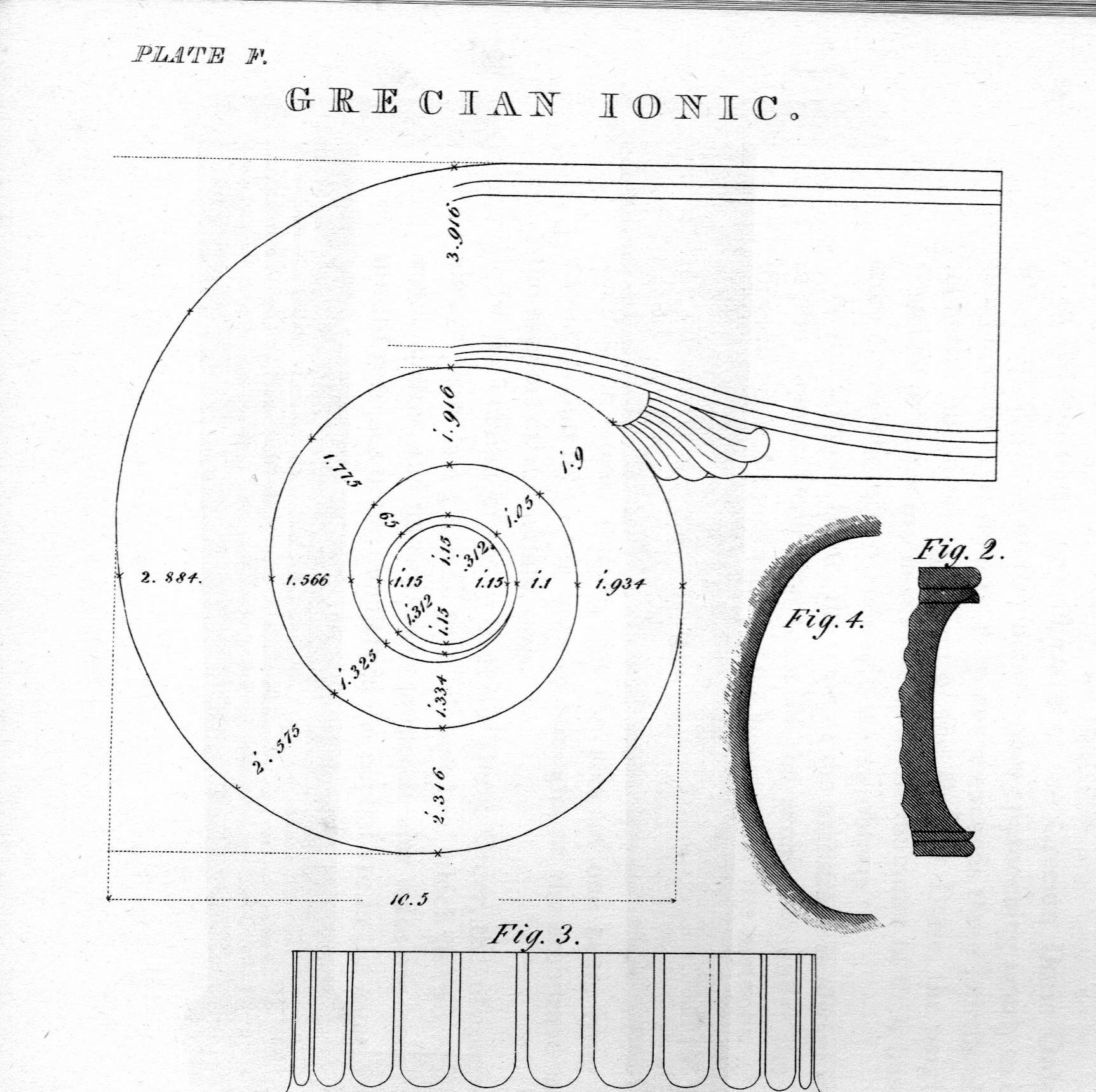
However, his revised 1827 edition includes the drawing above and also this diagram. "Plate F, From the Inside of the Portico of the Temple of Minerva, at Athens."
"Fig. 1. Volute of the capital, with the measurements in feet, inches, tenths, hundredths, & etc."
A footnote explains how to read Feet, Inches "and the decimal parts".
The Architect, or Complete Builder's Guide, written in 1839, has this drawing, Plate X. Asher Benjamin notes, "The carver will find it to his advantage to imitate these drawings faithfully, and thus escape the censure deservedly cast upon the many clumsy, awkward productions of this capital, which may be seen in both town and country."
Benjamin's books were published through the 1850's.

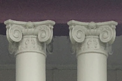
Then there's a break - I've found no English language 'how-to' pattern book instructions on volutes during the height of the Industrial Revolution. Ionic volutes were used: here on c.1896 porch columns. Probably these were created by craftsmen for a company which specialized in plaster and wood composites. They are probably available today.
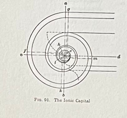
In 1903, in The American Vignola, William Ware describes how to construct a volute, "The vertical line a b, Fig 91, through the center of the eye of the Volute, and the horizontal line c d, will mark in the circumference of the eye the four corners of the square within which a fret whose angles may serves as centers..."*
6 sentences; 22 lines of instructions. This is a small drawing at the bottom corner of a page.
Architectural Graphic Standards' first edition was published in 1932. This page in every edition I own: 2nd -1936, 3rd -1941, 4th -1953, 5th - 1966, but not the 8th - 1988.
The pages are quite yellow - I've toned them down here to make them more legible.
The 8th edition of Architectural Graphic Standards, 1988, no longer dedicated a page to Ionic details.
The last 2 pages of the book, titled Classical Orders at the top and CLASSIC ORDERS at the bottom, are a crowded introduction to centuries of architecture.
Here's about 2/3 of the second sheet. The architects who complied the page are credited not their sources.

Do I have a conclusion? Not really.
I looked for the Golden Section and didn't find it. I read convoluted and simple language as people who knew construction explained with words how to draw something complex. Many descriptions expected experience using compasses. I appreciated the authors who said, "Practice!" Words help; they are not a substitute for drawing.
Books not listed here are in my bibliography.
Asher Benjamin, Practice of Architecture and The Builder's Guide, new introduction by Thomas Gordon Smith, De Capo Press, New York, 1994.
Batty Langley, The Builder's Director or Bench-Mate, published first in 1754, London, reprint, publisher unlisted.
William Pain, The Practical House Carpenter, or Youth's Instruction, London, 1794. reprint by Dover Publications.
Ramsey/Sleeper, Architectural Graphic Standards, John Wiley & Sons, Inc., New York
Giacomo Barozzi daVignola, Canon of the Five Orders of Architecture, John Leeke, translator, published by William Sherwin, London, 1669.
Vitruvius, Ten Books on Architecture, edited by Ingrid D. Rowland, Thomas Noble Howe, Cambridge University Press, 1999
*Wm. R. Ware, The American Vignola, 1903, Dover Publications, 1994, p. 30.
*Book 3, Chapter 5, paragraph 8, translation by Ingrid D. Rowland; Viruvius, 10 Books on Architecture, Ingrid D. Rowland and Thomas Nobel Howe, Editors, Cambridge University Press, 1999.
Wednesday, July 27, 2022
The Baptist Church of Streetsboro, Ohio, Part 1
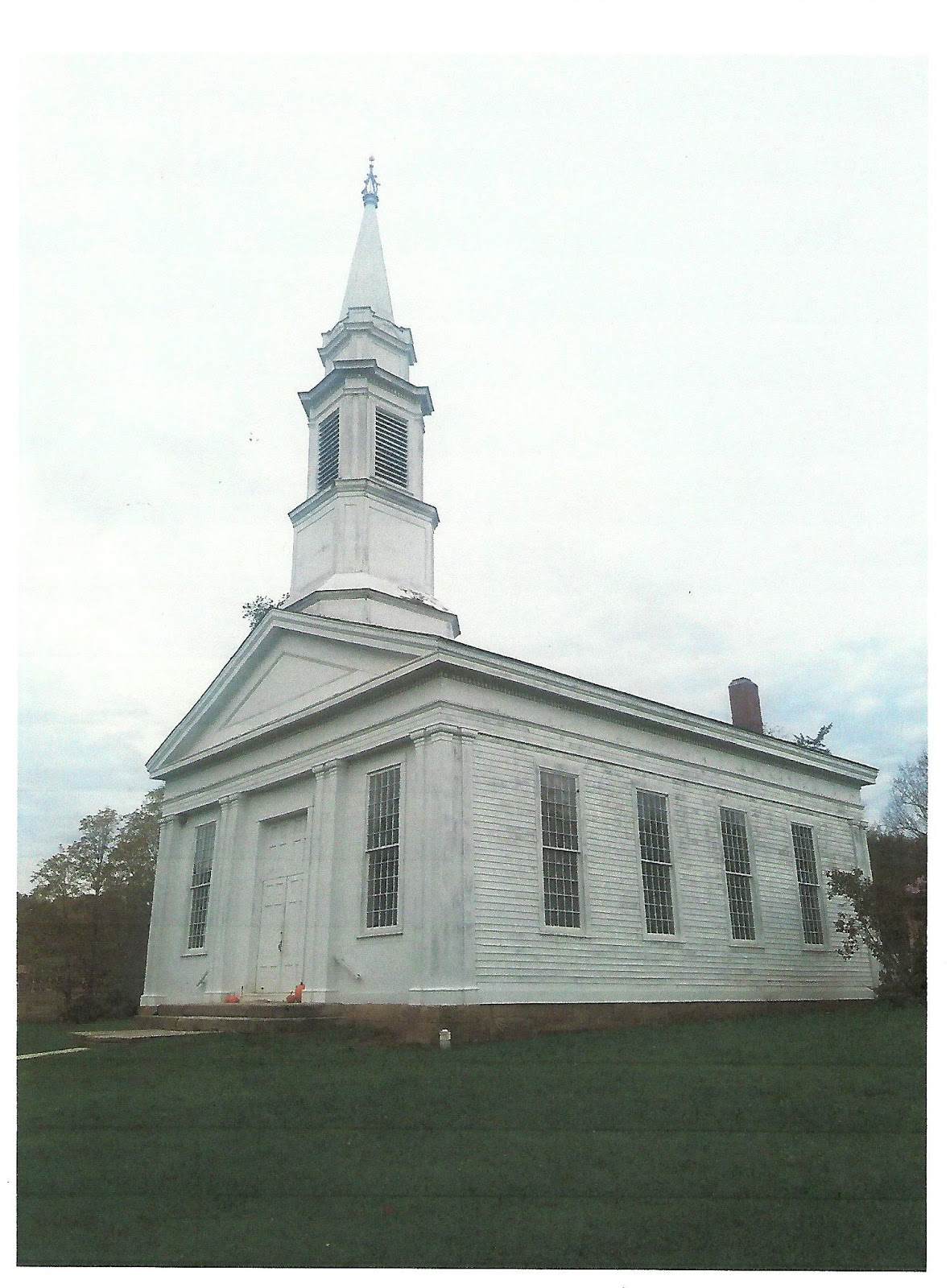
This is the Old Baptist Church at Streetsboro, Ohio, built about 1820.
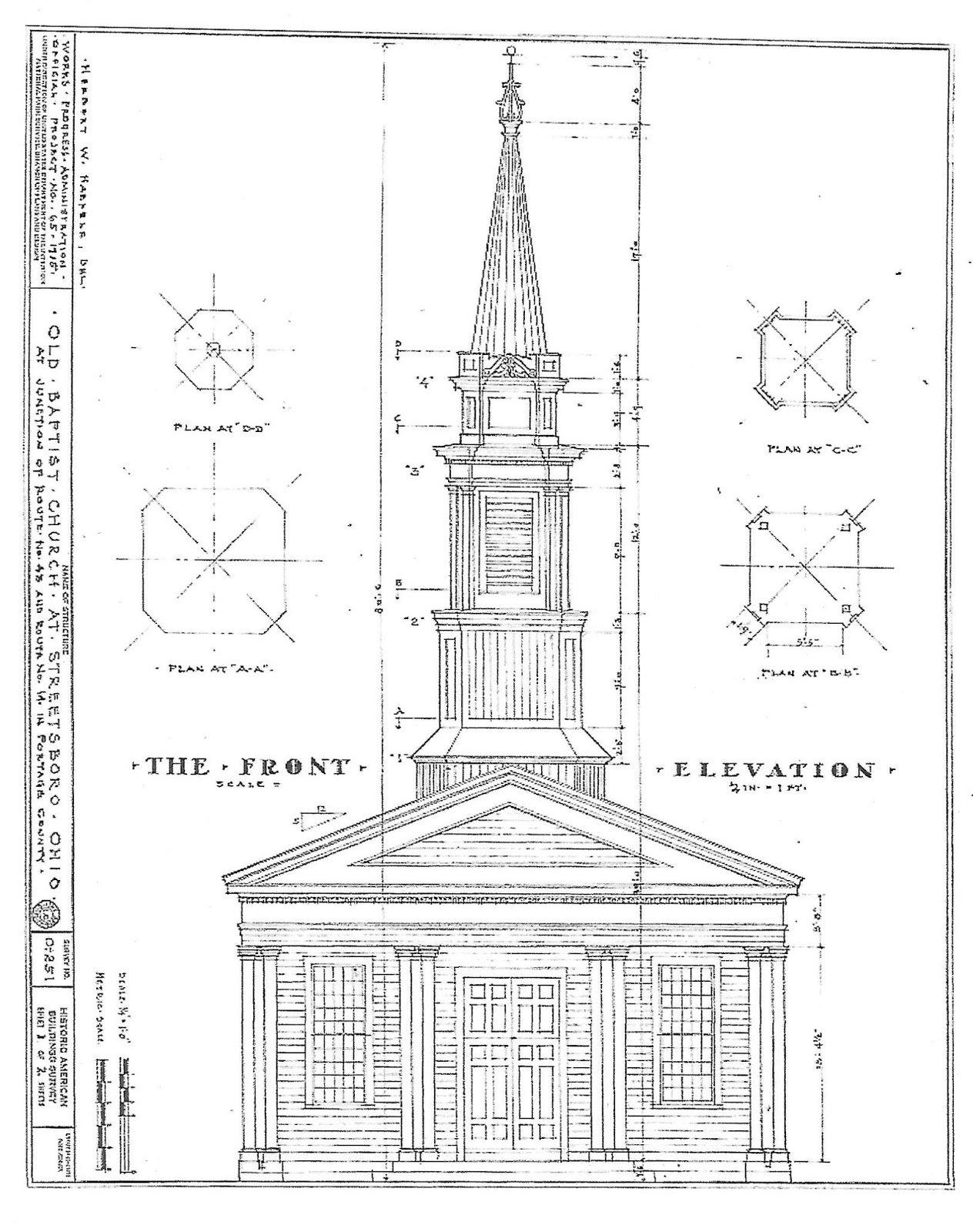
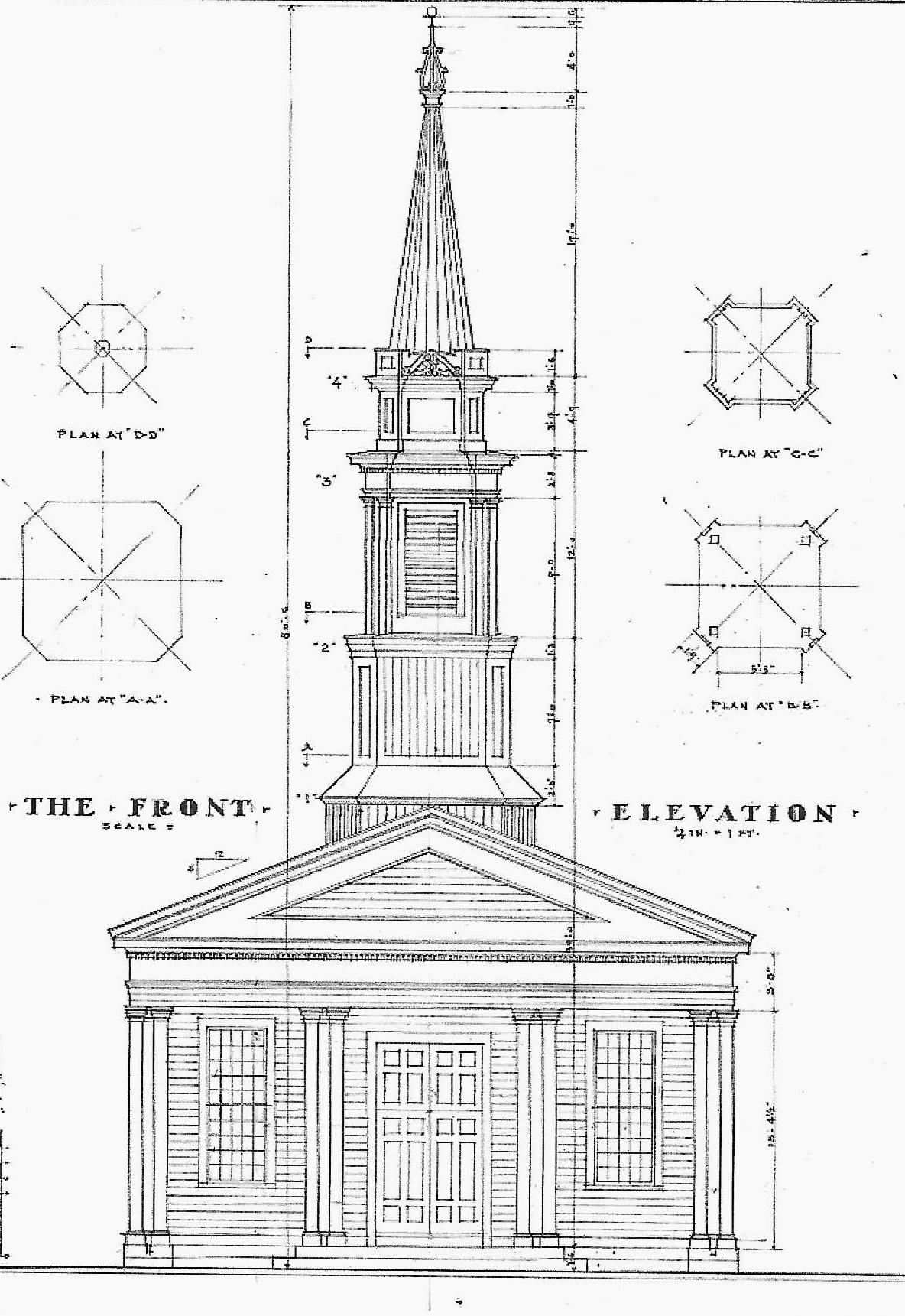
Here are the HABS drawings.
I wondered about its geometry. What framing traditions had the master builder brought with him to Ohio?
It looks linear, simple, obvious. Is it?
I explored the plan and elevation. While many forms of the Lines created by circles and squares worked pretty well, nothing quite fit.
I went back to the basics, the construction: What did the carpenter do? In what order?
He was asked to build a church about 'so big' - here about 36' x 50'. He laid out a rectangle using the 3/4/5 Triangle. The HABS drawings are blurry and tiny. The dimensions appear to be 38'-4.5" wide by 51' long, 3 units wide by 4 units long. (The length is about an inch too short.)
The triangles are ABC and ADC. They could also be ABD and BCD. The 2 layouts cross in the center.
The carpenter could check his diagonals, just as workers do today. When the diagonals were the same length the floor frame was square.
The bents for the frame were naturally the same width as the floor. It seems possible that the framer used the floor of the church for his layout. I had seen this in an upstate NY barn. I wrote about it here:
https://blog.greenmountaintimberframes.com/2014/12/04/geometry-in-historical-frames-a-guest-blog/
The elevation of the front of the church appears to be 2 squares wide. But the pediment did not come easily from that form - slightly too big.
However when I laid out the frame based on Lines laid on the inside edge of the sill and posts, everything fit and the peak of the bent, the location of the ridge of the church was the center of the rectangle. So simple, so easy!
How was it to the framer's advantage to lay out the frame from within the frame, not outside?
He needed at least 3 bents, perhaps as many as 5. He needed consistent marks for lengths and widths of all members and for each mortise and tenon. The Lines laid inside the frame would not be disturbed while the frame was laid out and marked. The timbers could be moved off the floor to cut the joints; another bent could be laid out. Or the bents could be stacked on each other.
Modern framers using timber and dimensional lumber stand within their work, measure, mark, and check from inside. Then they cut the lumber someplace else. Why not this earlier framer too?
After the bents and the roof trusses came the walls and the windows.
The spacing of the windows and their width comes from the rectangles that are within the original larger rectangle.
The green lines are 2 of those rectangles, the dashed lines with arrows on the left show the window frame locations. The green dashed line with an arrow on the right ( top left) is the width.

The geometry of the bents determined the shape of the facade, the height of the pediment. The front elements of the church - the pilasters and a grand door - were designed after the frame. The front windows were in place, therefore the pilasters needed to be equidistant on each side.
The door went in the middle, that's custom. Then there was the left over space in between. (See more about this below.)

The framers also had to provide support for the steeple. As I have no drawings of the side elevations, nor do I know the location of the bents. I do not know quite where the steeple sat: directly on the front wall? a few feet back? I would assume a bent supported the front and back walls of the steeple. The diagrams do show how the width of the tower and the size of the clipped corners were determined: it was a square with its corners cut off.
Carpenter squares began to be manufactured in the States - not imported from Britain - around 1820. They had true 90* corners and consistent dimensions. 3/4/5 triangles and rectangles were easy to lay out accurately. An inexperienced carpenter could erect a simple frame without much worry. Or, as may have happened here, a master carpenter working with church members as a volunteer crew could expect his crew to build a reasonably accurate frame.
Part 2, the design of the exterior of the church is here:
https://www.jgrarchitect.com/2018/04/the-baptist-church-of-steetsboro-ohio.html
7/27/22: I wrote this post in 2018. When I reviewed it recently, I saw how much needed to be revised, simplified; how much I'd learned about using geometry in construction during the last 4 years. Understanding Practical Geometry (the name Asher Benjamin and Peter Nicholson used) is an on-going exploration.
Tuesday, July 26, 2022
The Baptist Church of Streetsboro, Ohio, Part 2
The Streetsboro Baptist Church, built c. 1820: the second phase of its construction - its decoration - the front facade and the steeple.
The first post* discussed how the framer used the geometry of the 3/4/5 Triangle to layout the floor, the bents, the walls and windows, the roof and steeple. After the framers made the building 'tight to the weather', joiners would often be responsible for the finish work: window sash, doors, molding. Different trades had different skills and tools.
I think this division of labor happened here.
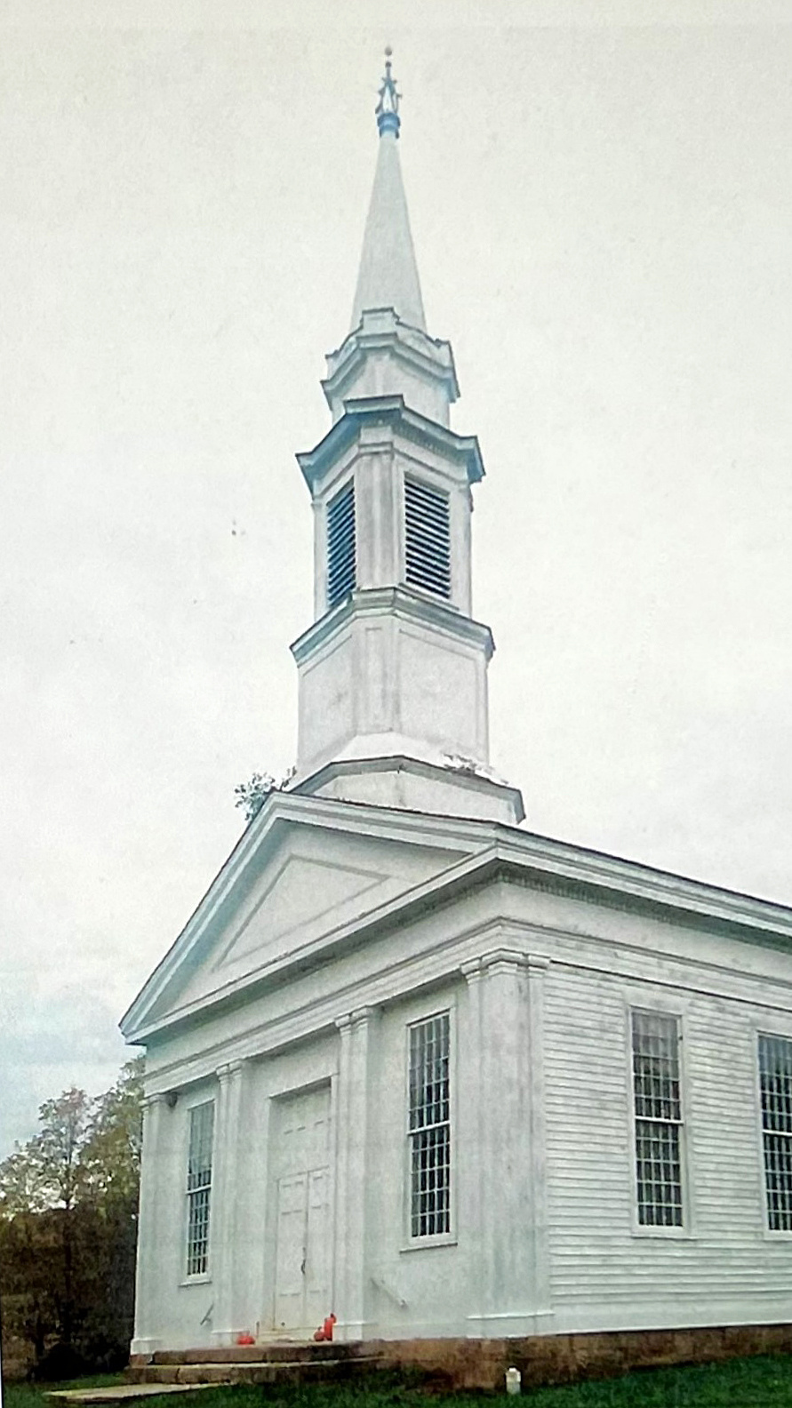
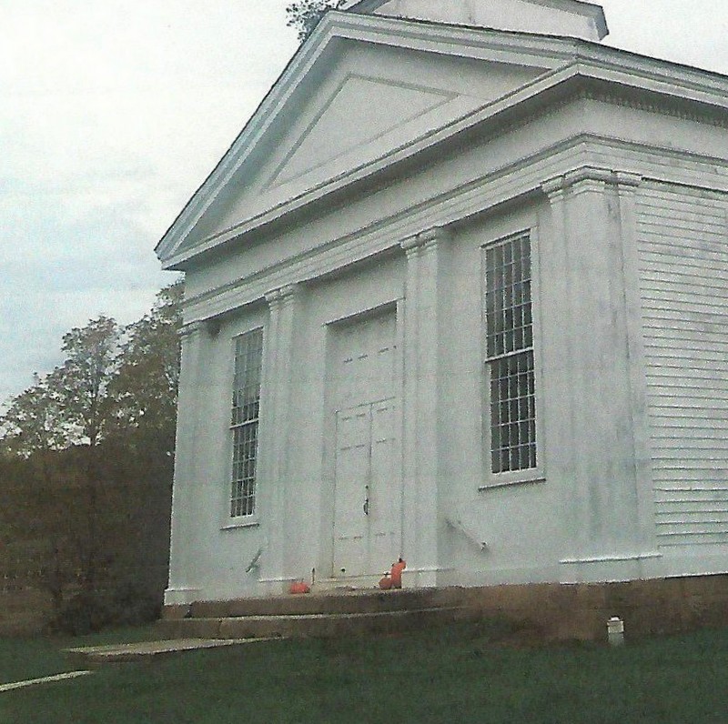
The church front on a cloudy day in October. It is a handsome building. It is also a box decorated with boards and moldings. That's what I am looking at in this post.
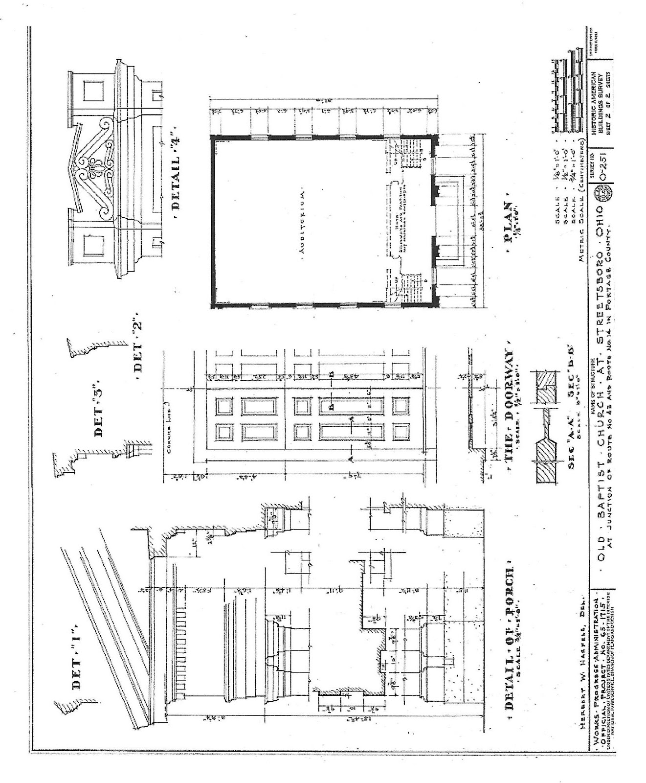
The HABS drawing is below.
The windows had been set by the framer when he laid out the floor plan, the walls, and the roof frame. The black lines show what the front wall would have looked like when the joiner began his work. Holes for windows, a space - perhaps a larger framed opening - for a door, a triangular gable.
The congregation expected that this box with a roof would become a modern Greek Revival church.
Of course the joiner was considering the pediment, the frieze, the architrave. the water table. He also needed to lay out a facade which has grace and rhythm as well as symmetry.
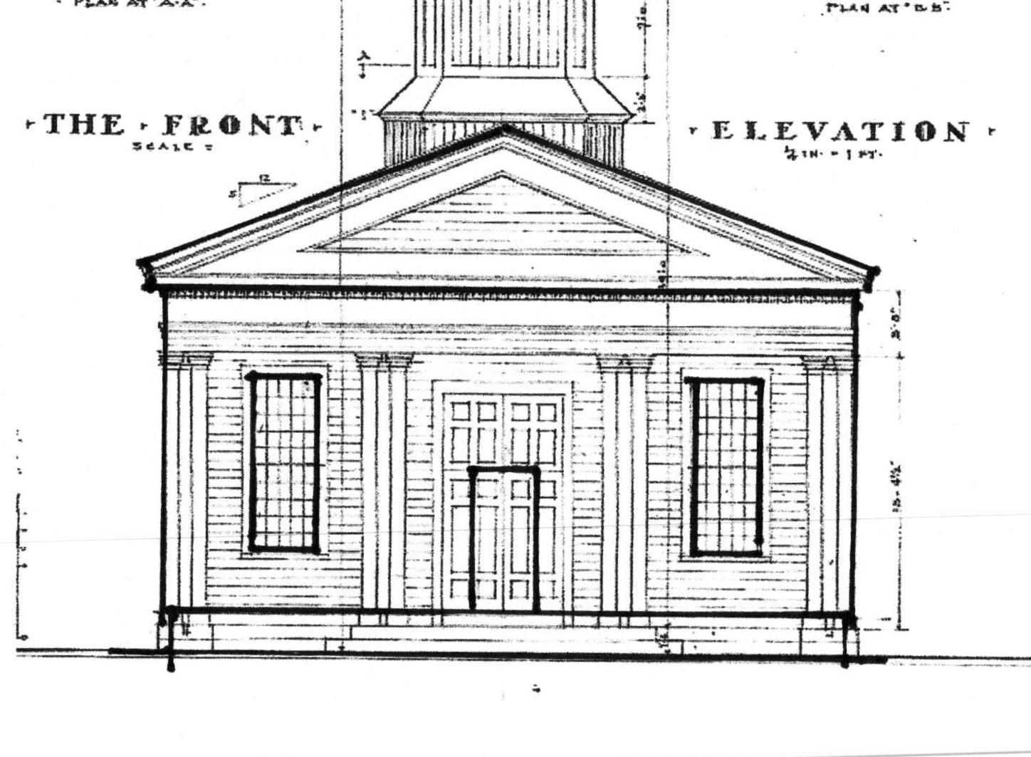
Here is the geometry of the facade as the framer knew it: 3 bays with their height from the floor to the roof trusses, their width between the corner posts, and a door, centered but of undetermined dimensions. The windows are centered within the 3/4/5 rectangles of the frame's rhythm. Their shape is 2- 3/4/5 rectangles.
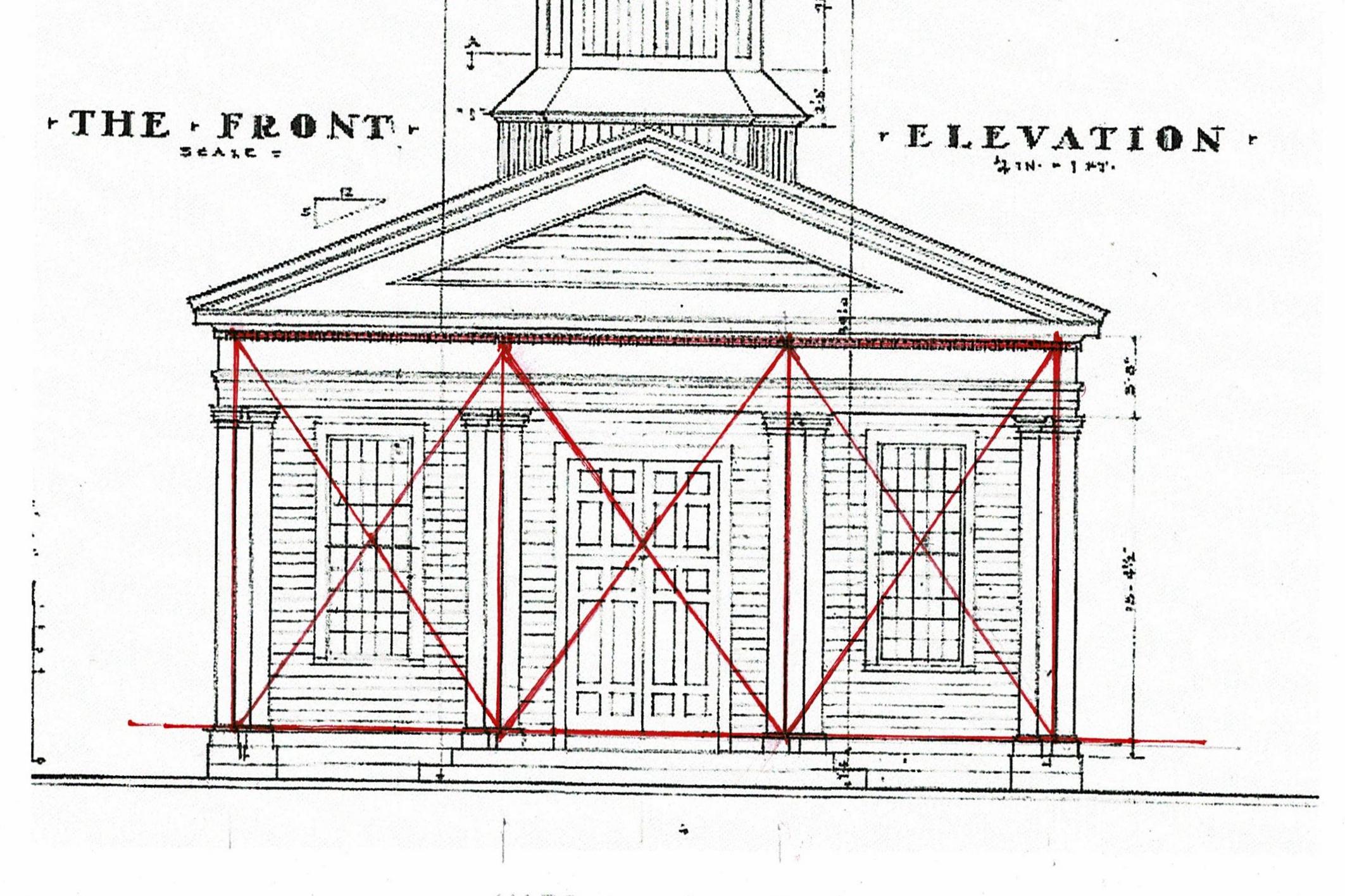
I think, the joiner chooses to balance the windows first, to set them as supporting wings to the central door. The corner boards grew to become paired columns balanced by 2 more columns on the other side of the windows. Note that the columns are not on the lines of the bays, therefore the center bay is slightly wider than the side bays. The window bays became back drop to the central bay with its double door and paneled transom.The joiner 'adjusted' the geometry; but the window bays' symmetry is so strong it is hard to catch. The tall, broad main door, recessed in the main bay, then surrounded by the columns and the frieze, becomes the focus.
The joiner 'fooled the eye' and created a dynamic facade, much better than 3 equal rectangles would have been.
The framer built the base which supported the steeple. Its dimensions at the roof are based on the 3/4/5 Triangle.
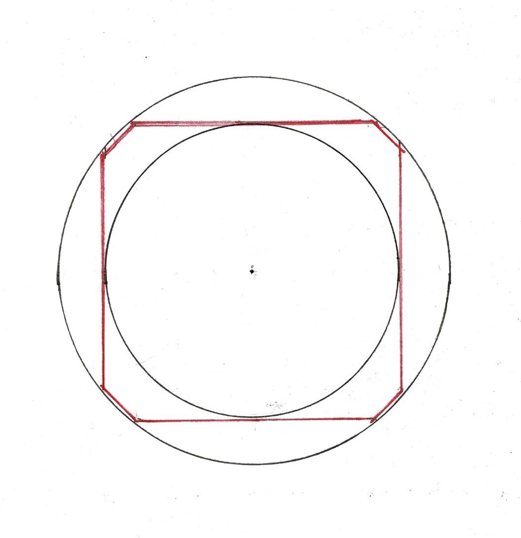
The steeple uses neither the geometry of the frame nor that of the front facade. It is a series of blocks, decreasing in size, with their corners clipped. The design uses the square and the circles that fit within and without it. Was it the work of the same joiner? **
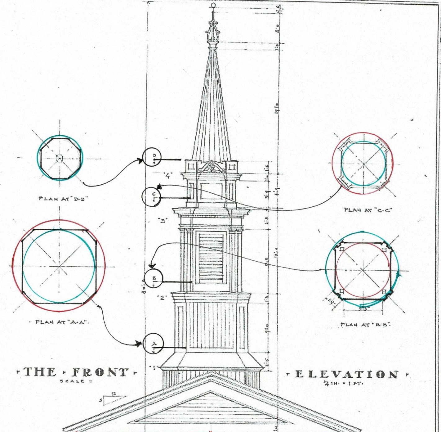
The HABS drawing shows the steeple sections.
Here I have added the circles - In 'A' the red circle is outside, the green inside. In 'B' that green circle is now outside, a new smaller red circle inside. 'C' continues the progression with the red circle from 'B' now the outside. The green circle of 'C' is the base of the spire.
The steeple layout follows the drawings of James Gibbs in his book "On Architecture", published in England in 1728. Copies were in the Colonies, available to builders. I have written about Gibbs' steeples here: https://www.jgrarchitect.com/2022/02/james-gibbs-steeples.html
These HABS measurements are too simple for an in depth study of the steeple geometry.
The shapes that make up the tower are a series of blocks with related faces all derived from the simple manipulation of the square: a complete square, 2 squares, one square, half a square (the base for the spire).
The spire's height uses the width of the steeple's base as its unit of measure: it is 1.5 times as tall as the base is wide.
The paneling, edge moldings, and the series of roofs as the tower extends create the steeple.
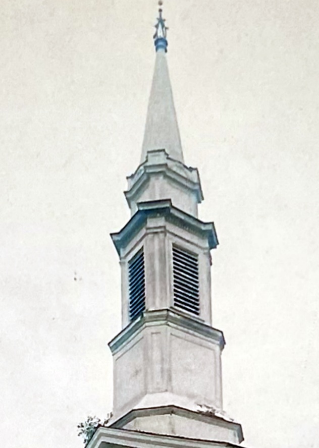
Look again at the photographs.

The door itself is approximately square, the transom: half a square. They are the same size as the section of the steeple which holds the bell.
The wall of that bay acts as a setting, a frame for the door. The columns and architrave are a second frame.
Look again at the photographs.
The church's grace and presence come from simple proportions in the design and the understanding of how light and shadow give life to the parts themselves and thus to the whole building.
Here is what Asher Benjamin wanted the joiner - and by extension, we who see the church - to understand about moldings :
"...the bending, or turning inward, of the upper edge of the Grecian, or quirk ovolo, when the sun shines on the surface [and] causes a beautiful variety of light and shade, which greatly relieves it from plane surfaces, and if it is entirely in shadow, but receives a reflected light, the bending or turning inward, at the top, will cause it to contain a greater quality of shade in that place, but softened downward around the moulding to the upper edge." ***
* Part 1: https://www.jgrarchitect.com/2018/04/the-baptist-church-of-streetsboro-ohio.html
** The Sandown, NH, Meeting House and Gunston Hall in Virginia are good examples of this separation of craft. At Sandown a skilled joiner built the main door and the pulpit, perhaps the wainscotting and box pews. George Mason of Gunston Hall brought William Buckland from England to create the porches and interiors for his new brick house.
**Asher Benjamin, The American Builder's Companion, 6th edition, 1827, R.P. & C. Williams, Dover Publications reprint, Plate IX, Names of Mouldings.
Sunday, June 19, 2022
James Gibbs' Of Architecture,
Draughts for a Menagery,
Part 2 of 2
The second menagery in James Gibbs' On Architecture* was never built. In Part 1 of 2, I wrote about the first one which was built at Hackwood Park, an estate near London. It is still standing.
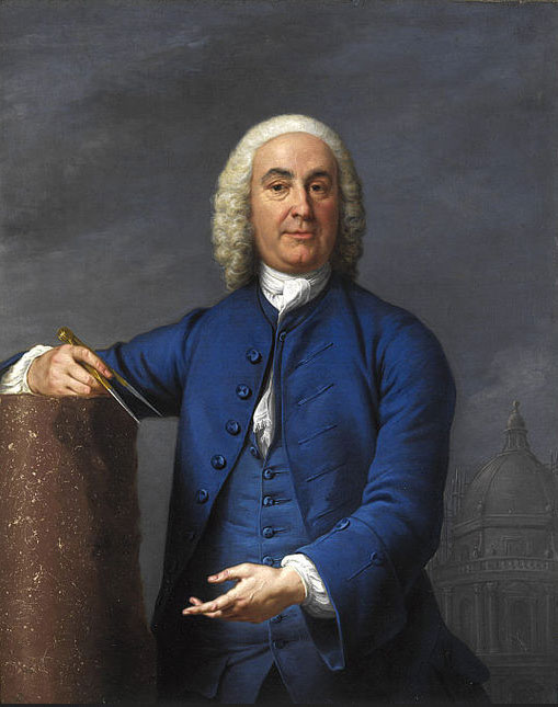
Here is Gibbs' portrait with his compass, the mark of his profession.
Gibbs' expected "any Workman who understands Lines" to be able to execute his designs. What would a workman have seen in Gibbs' drawings? What could I see? Did I understand Lines?
The first option was so simple. I was looking for an equally direct layout for this second design. I could find only complex solutions. They worked, but they were not direct. For 3 months the obvious design was right there and I couldn't see it. I put the puzzle aside several times.
The second menagery in James Gibbs' On Architecture* was never built. In Part 1 of 2, I wrote about the first one which was built at Hackwood Park, an estate near London. It is still standing.
Here is Gibbs' portrait with his compass, the mark of his profession.
Gibbs' expected "any Workman who understands Lines" to be able to execute his designs. What would a workman have seen in Gibbs' drawings? What could I see? Did I understand Lines?
The first option was so simple. I was looking for an equally direct layout for this second design. I could find only complex solutions. They worked, but they were not direct. For 3 months the obvious design was right there and I couldn't see it. I put the puzzle aside several times.
This 'menagery' was to be a welcome destination for those strolling through the Hackwood Park estate grounds. Built of stone, the menagery would not have been as dark as this image.The 'draught' elevation accentuates the quoins and articulated arches, to give the workmen the necessary information.
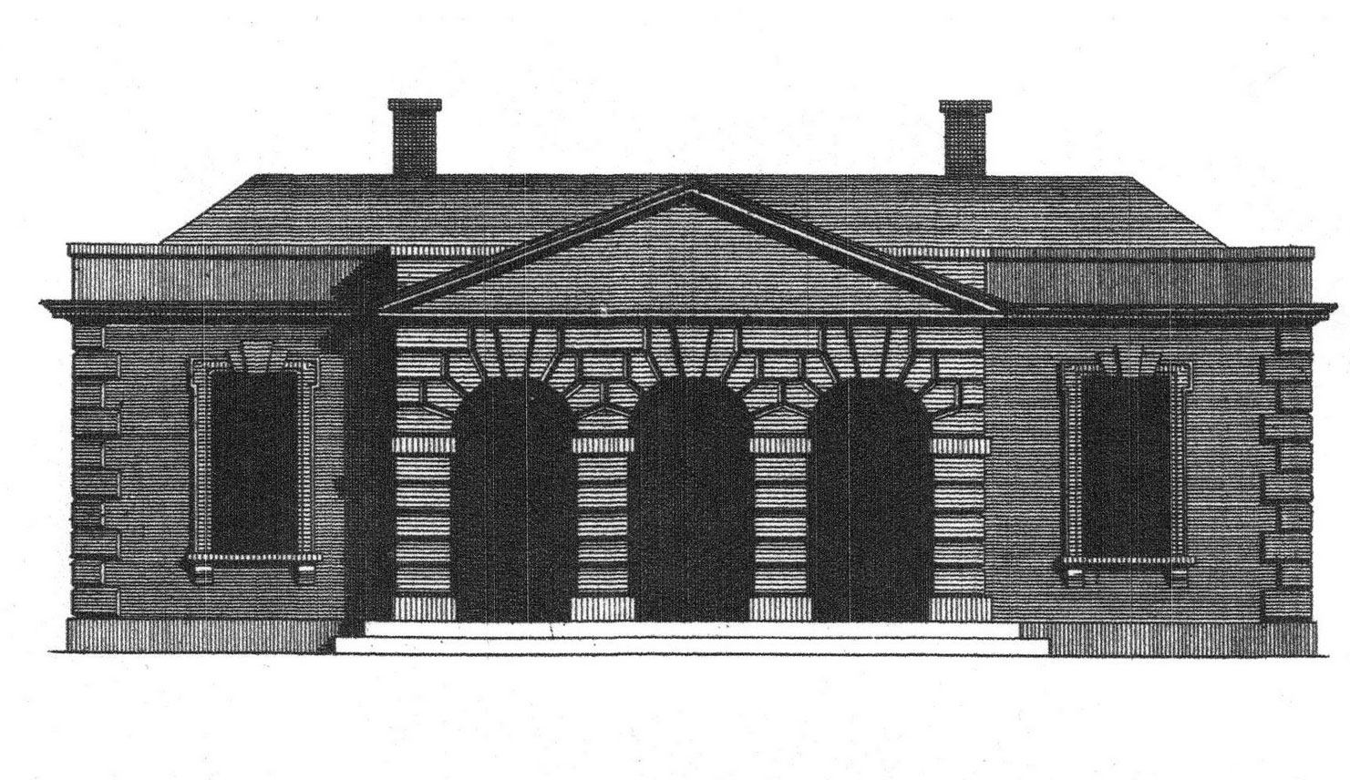
Like the design which was built, the pavilion required a gracious porch with a room on each side: one for serving and drinking tea, one for the quiet perusal of books about nature, especially birds. The living quarters for the staff who took care of the estate's pheasants were around the back.

Today a plan usually lays out the exterior dimensions. Here the exterior is to be stone, perhaps ashlar or split, with rusticated, oversized arches and quoins (the corner blocks). Using inside dimensions to layout the plan allowed the exterior dimensions to vary.
Note that Gibbs' drawing of the exterior stone facade is structural. The blocks interlock on the corners; the arches and key stones interlock with the wall.
The floor plan begins with the central form: the porch and caretaker's quarters. Its size is determined by 2 3/4/5 rectangles overlapped at their mid-points.
Gibbs assumes the workmen who might copy his 'draught' know how to build walls; he is not providing a construction document.

The wall between the porch and the living quarters is set beside the center of the rectangle found by drawing the diagonals of the main pavilion. This makes the porch large and gracious. It is also the way a mason sets lines today, building beside his lines.
A workman could true his rectangle to center the doors on the walls. Note the red line.
.jpg)
The lines from the corners to the center locate the center lines for the arched columns.
I have left out many lines here for clarity. They could be added to check the work.
I call this 'The rule of Thirds' because artists who use these lines as a design tool call it by that name. It's the 3x3 pattern that appears when we edit cellphone pictures. **
.jpg)
The wings of the menagery are set back 1/4 of the depth of the main block in the front and the back - note the red line with arrows As the geometry here is the 3/4/5 rcctangle it is fitting that the wings' length is proportional to the main pavilion's length: 6/8 or 3/4.
.jpg)
The wings are themselves both 3/4/5 rectangles.
The 3/4/5 rectangIe was a common way to add a wing to an existing building. If the mason set his length against the central form at 4 units and his width at 3 units, his wing would be square against the main block. His stone work would be true. I have drawn the 3 x 4 units here. I have also left my pencil marks for further information (enlarge the drawing!)
While this menagery design is more complex to write about than Gibbs' other design*, it is quite easy to lay out with a compass and straight edge. A trained workman would have known the steps. The 3/4/5 rectangle and the Pythagoras Theorem are used today.
The elevation? It's 4 squares and the same pediment layout that Gibbs used on the menagery design which was built. The inside dimensions govern. The red arcs drawn show the floor width of the rooms are also the height of the elevations.
A note: the windows are centered on the rooms' inside wall, but not on the exterior width of the wing. The quoins are such a strong visual vertical that they appear as an anchor. The windows were centered on the rest of the wall.
The pediment is drawn following the rules described by Serlio. For step by step instructions, refer to Part 1 of 2 of this post of the draughts for the Menagery.*

* Gibbs' book On Architecture, published in 1728, includes 150 plates: plans, elevations, sections and perspectives of buildings Gibbs had designed and built. The quote is from his introduction, page i. A reprint is available from Dover Publications.
Part 1 of 2, the post for Gibb's design of the Menagery which was built is here: https://www.jgrarchitect.com/2021/12/james-gibbs-book-of-architecture.html
** I've posted about The Rule of Thirds in more detail here:
https://www.jgrarchitect.com/2020/08/lesson-6-rule-of-thirds-part-1_21.html
https://www.jgrarchitect.com/2020/08/lesson-6-rule-of-thirds-part-2-serlio.html
![]()
Thursday, April 21, 2022
The Parson Capen House, 1683, Topsfield, MA
This post, first published in 2014, has been revised based on a better understanding of the geometry.
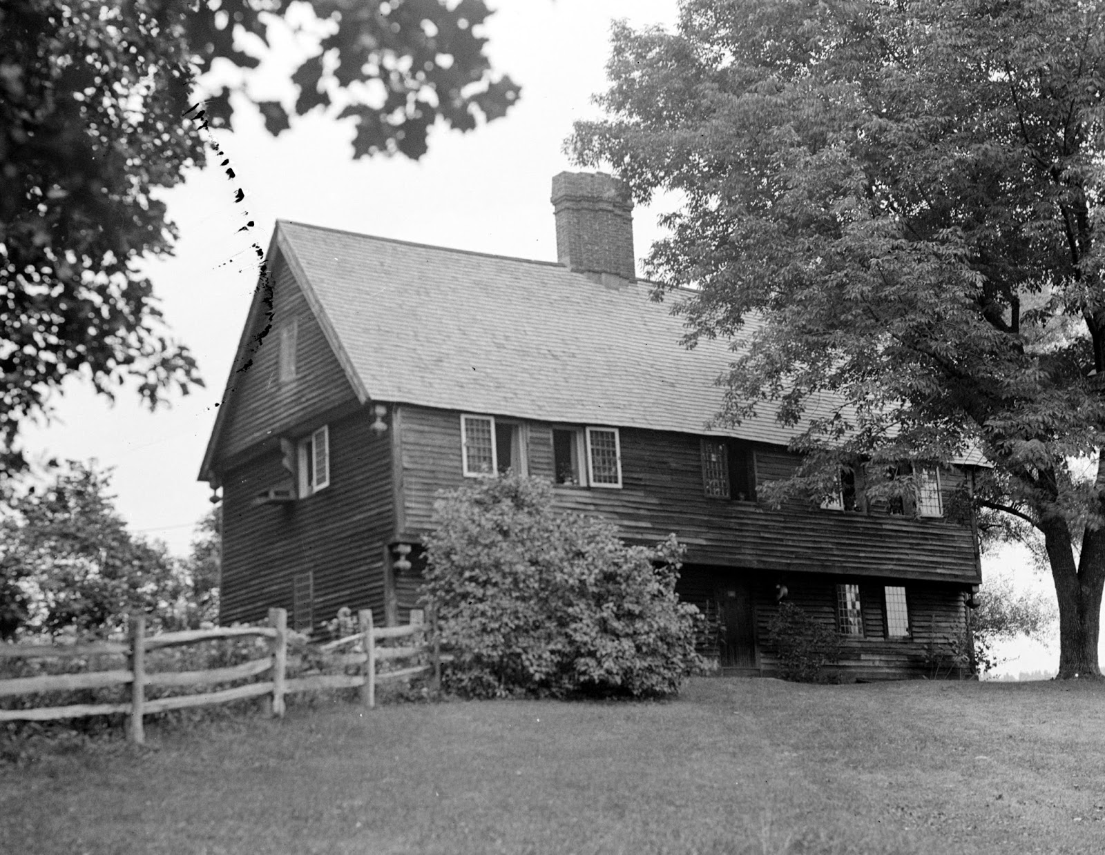
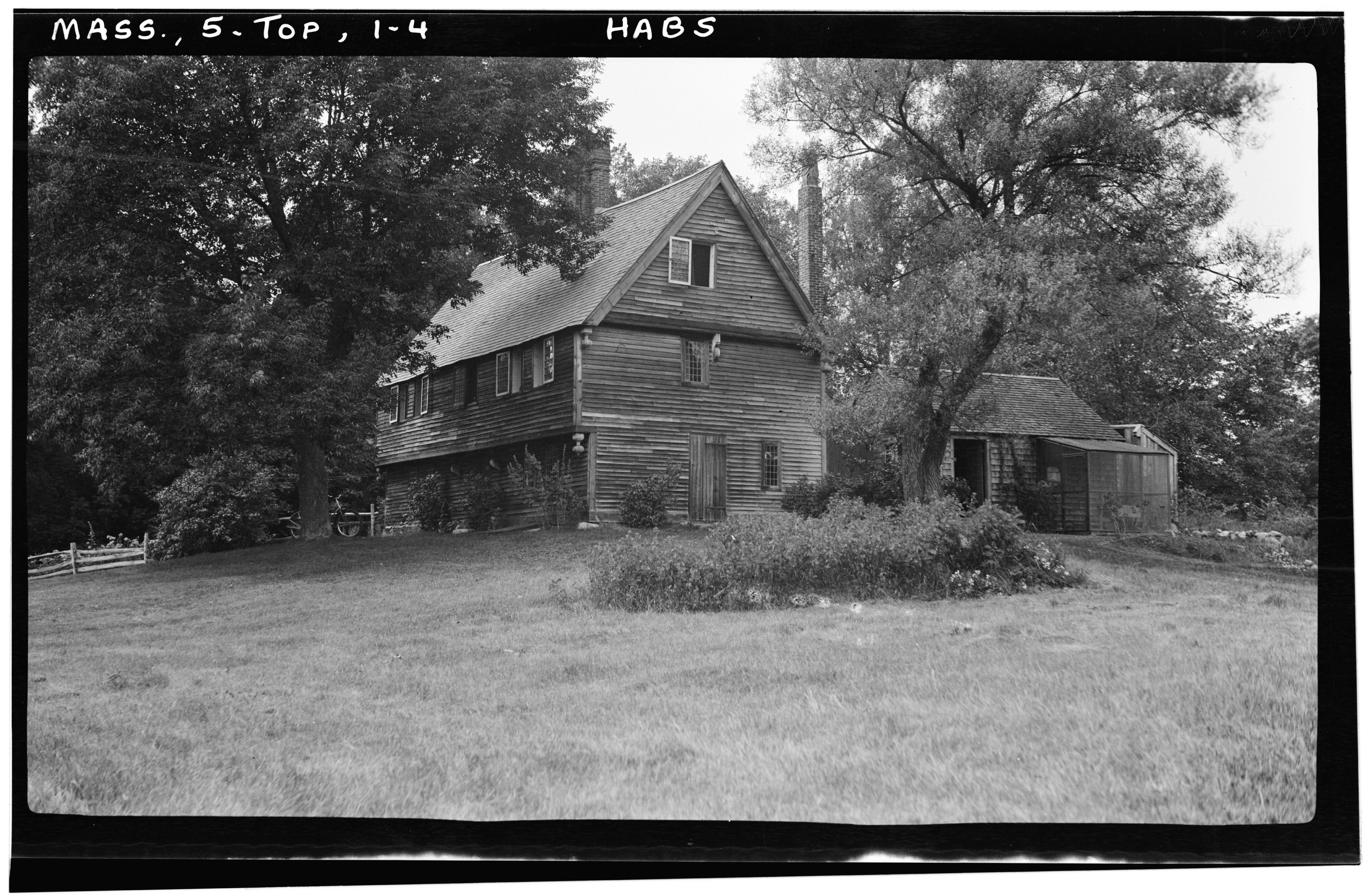
Parson Joseph Capen built this house in 1683 in Topsfield, Massachusetts. He ministered to the town from 1682 until his death in 1726.
The story about this house: It is still here because it was owned by an old Boston family with extensive land holdings.Their herdsmen drove cattle to market in Boston along Rte 1 (which is practically next door to this house) and used the house as a way station on their trips into the city. So it wasn't torn down, updated, or abandoned. We are lucky.
The pictures are from the LOC HABS archive. Note the drops and brackets. The windows are casements; in the picture they have been swung open.
For more information and photographs in color see http://www.topsfieldhistory.org/parson_capen.shtml
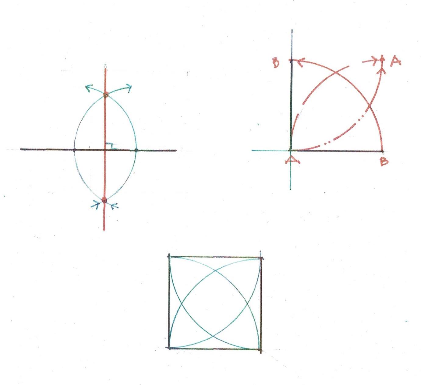
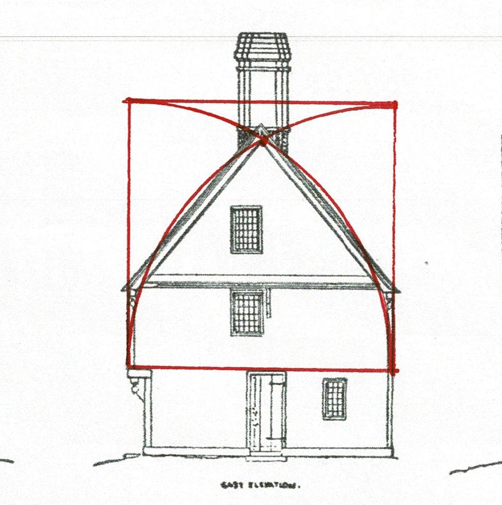
The geometry for the house is based on the square.
Here is how a square is derived using a compass, a straightedge and a scribe.
Once a carpenter knew his geometry he could layout a square in fewer steps.
The square with its arcs gives the carpenter 4 points - where the arcs cross each other - for dividing his square in half horizontally or vertically. This could have been used for the hall and the second floor beams.
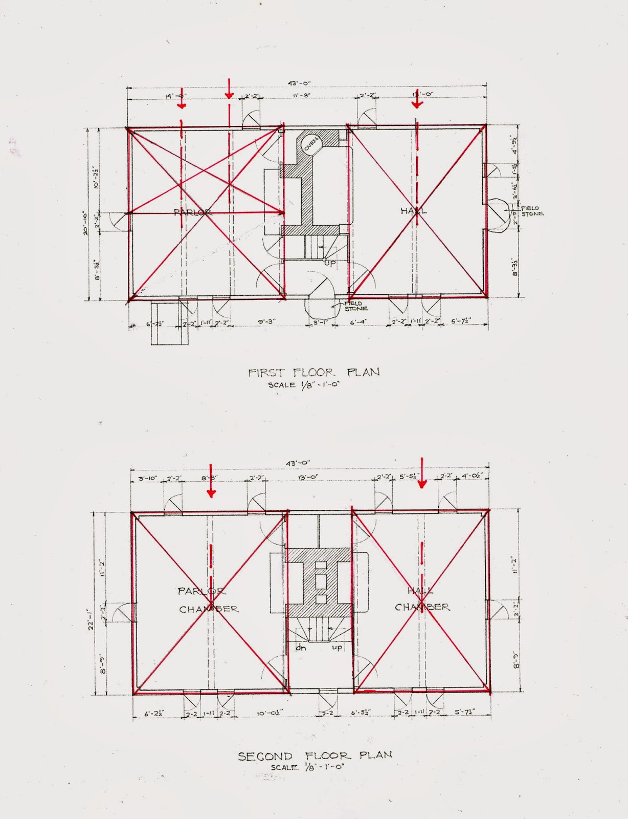
The chimney and fireplaces were to be in the middle of the house.
So the builder laid out the house foundation from the chimney block.
The diagram shows in the center the brick which would have formed the back wall of the 4 fireplaces with 2 square spaces on either side: the parlor and the hall.
Next comes the fireplaces themselves, on both floors, and the flues.
On the first floor the main masonry block is a square in plan, the oven needed half a square. Its flue joins the hall chimney.
On the second floor the chimney mass is square.
The house has 4 bents, one on each end and one on either side of the chimney mass. The fireplaces depths on the second floor determine where the 2 interior bents are placed.
It's possible there are bents across the rooms as well. However, since the summer beams on the first floor appear to be located over windows and the second floor beams do not match the first floor beams, I think not.
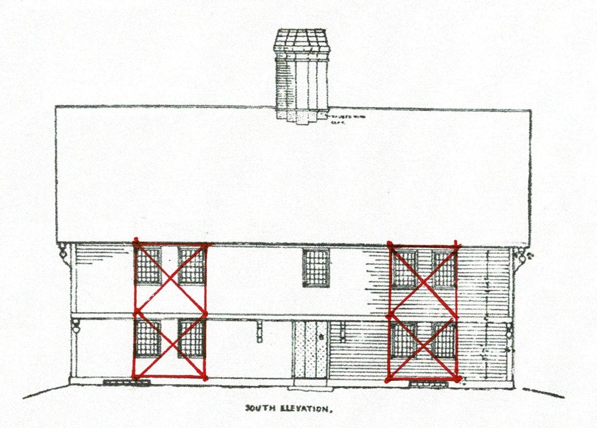
The Rule of Thirds was used to lay out the bents. It determined the heights of the floors and the placement of the windows. (The red arrows indicate ceiling heights.)
See this description for how the Rule of Thirds works: https://www.jgrarchitect.com/2020/08/lesson-6-rule-of-thirds-part-1_21.html
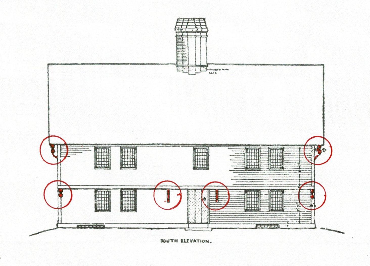
The cantilevered end beams for the second floor have drops below them. The beams for the interior bents have corbels. These are quite visible in the HABS photographs. The cantilevers for the roof also have drops, as well as corbels in the middle of the roof overhangs on the end elevations.
The second floor overhangs the first floor by about a foot on the south/front side. This was popular in England as a way to protect the daub and wattle walls from rain and wind. Here weather boards - known today as clapboards - covered the frame, but the tradition continued. The attic extends out over the second floor on the sides of the house for the same reason.
These HABS photographs are beautiful and clear. Click the images to enlarge them.
The roof pitch and the placement of the ridge pole might have been laid out from the second floor. I have seen this proportion - the crossed arcs of the side of the square - in other First Period houses, It may have been used here. I am currently exploring how a 12 pointed daisy wheel may be the base for the layout. I'll add more as I learn.
Note the corbel beside the 2nd floor window which supports the roof overhang.
Here is the front elevation with the drops and corbels noted. They accent the ends of the cantilevered beams which are the top plates of the bents.
The beams:
In the hall the beam which supports the second floor joists was set in the center.
The parlor, the room to the left, is larger. It needed 2 beams. So the space is divided into thirds. These beams are joined to the beam that runs between the 2 bents on this side. The windows were placed where a post would be located under those beams if they were part of bents.
On the second floor the ceiling beam are centered. All the beams appear to be set to the side of the lines, not on the line.
This drawing may be an accurate depiction of the front elevation. However, the plans are not quite consistent with this layout. The windows might be set equidistant from the corners of the house, or not. They may be centered on the second floor rooms, but not on those on the first floor.
Both sets are grouped together in the same geometry. The casement windows are all the same size.
The measured drawings for the Historic American Building Survey, HABS, were done at 1/8"= 1'-0", a scale which is fine for concept, but not good enough for serious consideration of construction details. They have very few dimensions. The drawings from 1916 do not quite agree with HABS. Some observations:
- *The Golden Section is not used here. I find that the Golden Section is about growth; houses are about stability.
- *The front door is not centered on the facade; if it were the door could not be opened back against the front wall. The brackets sit under the 2nd floor beams extended to support the cantilever.
4/21/22: I wrote much of this 8 years ago. The layout of the foundation based on the location and size of the chimney back still makes sense. I revisited the framing and the elevations, understanding that the layout begins with the framer who must decide where the bents will be; how tall; where the marks for the mortises and tenons will be. And how will the second floor and roof cantilevers be supported?
![]()
Tuesday, April 19, 2022
The geometrical design of Harmondsworth Great Barn, Laurie Smith
For Laurie Smith, my friend
Here are the front and back covers of Laurie Smith's last book.
The book is full of beautiful photographs of medieval framing and the history of the conception and construction of these barns' frames - from felling the trees to placing the aisle braces.
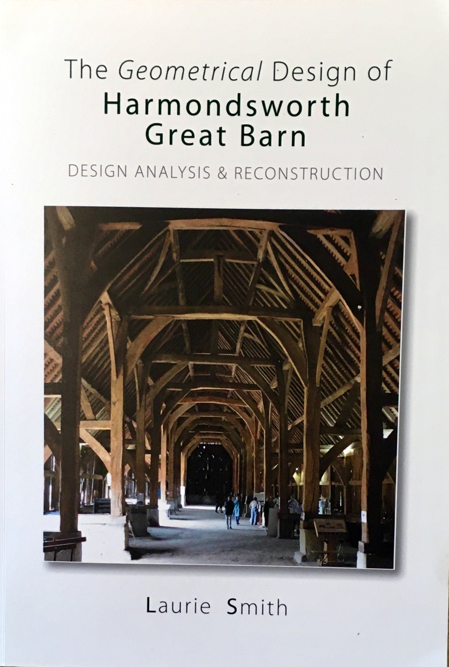
Of course, as the book is about Geometrical Design, it's also is full of daisy wheels and explanations of how they were used to design the Harmondsworth Great Barn.
Laurie Smith was a Geometer, probably the best. He researched, wrote, and taught architectural (aka 'practical') geometry. His language and his drawings are clear and engaging.

It is a book to read, think about, study. It can be read by a novice as well as one well versed in geometric construction. Laurie's first Drawing 1 is titled: "Names and Locations of the Frame's Timbers". It's accompanied by a Chart: "Heavy timbers needed for the barn's section". From that basic introduction he explains the geometry of the barn.
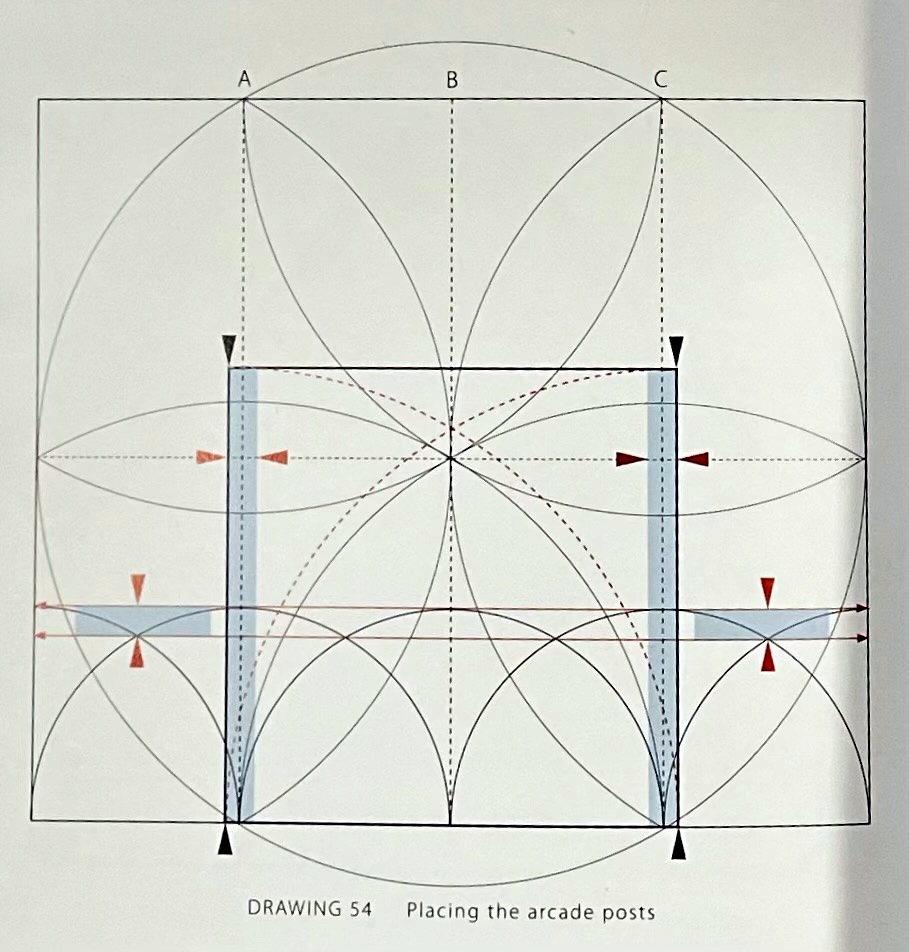
If at Photograph 39 you aren't sure what an 'arcade post' is, that first drawing is readily available. Using Photograph 39 Laurie explains how - with simple drawings, photographs, and the language of timber framing - arcade posts, arcade plate jowls and buttresses fit together and why they are important.
Then you understand Drawing 54.
Laurie doesn't just quote Vitruvius. He spends time with those terse sentences in Book I, De Architectura, exploring as a Geometer, whose tools are a compass and rule, what Vitruvius means when he writes a "...plan is made by the proper successive use of compasses and rule".
Laurie includes a carpenter's dividers, probably his own. He explains how they are 16.5 inches long, proportional to a rod which is 16.5 ft., and discusses 'stepping off'.

The geometric analysis of other great barns - The Barley Barn, Cressing Temple, Essex, and the Leigh Court Barn, Leigh, Worcestershire - is thorough and clear.
The Notes and Credits are good reading, not a perfunctory listing of people and books. There is much here to absorb, come back to, consider again.
Laurie finished the text, the geometric drawings, and the design in the summer of 2021. It was published that fall by Historic Building Carpentry in partnership with the UK Carpenters' Fellowship.*
He sent me a copy. I read it twice and told him how much I liked it. At his request I sent copies to a few of the timber framers in the States who had worked with him .
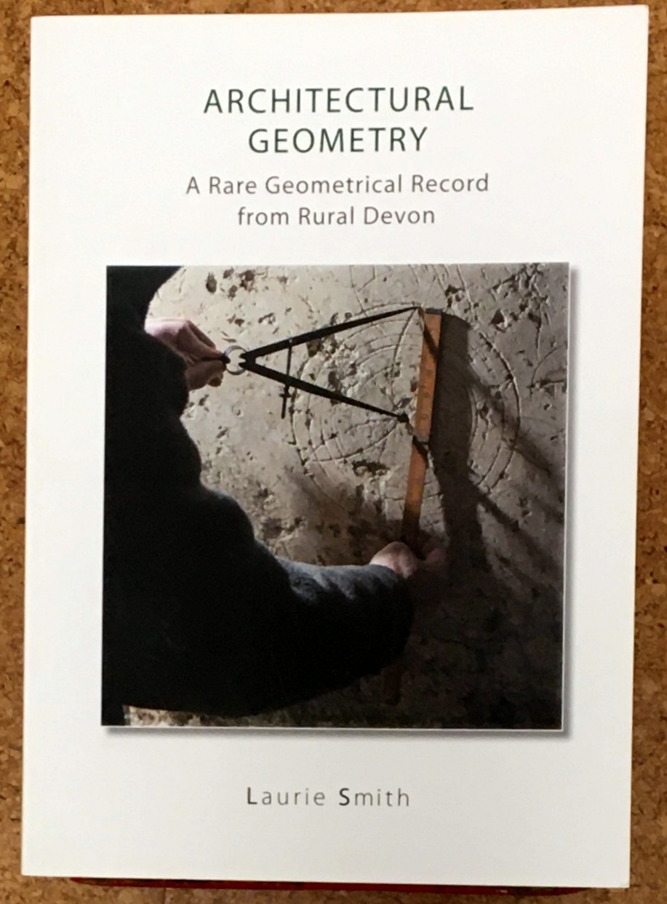
I wrote that I'd put a review on my blog as I had before for his book on a barn in Devon. Here's the cover of that book.
My review is:
https://www.jgrarchitect.com/2020/11/architectural-geometry-rare-geometrical.html
We enjoyed seeing that over 700 people had read that review. (now over 800)
We wondered how many had found his website through my blog post. He listed my blog on his website. I hadn't yet figured out how to list his on mine.
We talked about the geometry we'd explored and learned about in the last 8 years.
Then Laurie died, December 2, 2021.
Now it's hard to read his books. I want to send an email across The Pond , "Yes, and what about....?"
Then I remember that I read Durer, Serlio, Palladio and feel that they are speaking to me directly, 500+ years later. Like them, Laurie's spirit is in his book. His words share his awe, his joy, and profound understanding of the geometry he saw, knew so well, and loved.
*The Geometrical Design of the Harmondsworth Great Barn is available through the Carpenters' Fellowship, ( https://carpentersfellowship.co.uk/) in the UK. I act as the distributor in the States. Please contact me if you would like a copy @ $25., including postage.
![]()
Friday, April 1, 2022
Images from my talk on the Historic Practice of Practical Geometry , April 7, 2022
My talk for the Traditional Building Conference in Alexandria, VA, focuses on the geometry we used before and sometimes after we had standardized dimensions. I mention many pattern books and their authors with only brief introductions.
I have added links here to my blog posts that explore and add context to these ideas. I will add more.
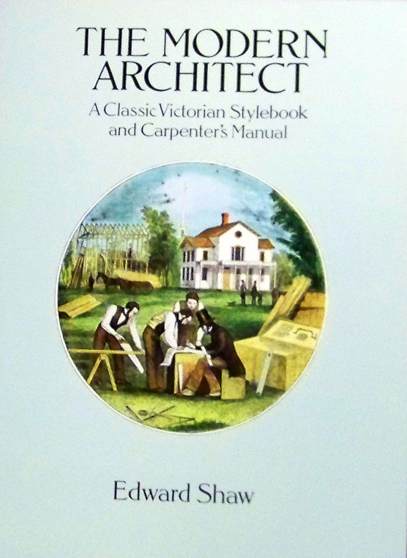
Edward Shaw's book includes these engravings.
The cover of his book shows the tools of a Master Builder (an architect) and his workmen.
My blog posts on Shaw are here:
https://www.jgrarchitect.com/2012/02/edward-shaw-uses-tools.html
This post puts him in context:
https://www.jgrarchitect.com/2019/10/portraits-of-master-builders-with-their.html
This post discusses his tools, and those of others, in detail.
https://www.jgrarchitect.com/2019/12/english-construction-tools-1669.html
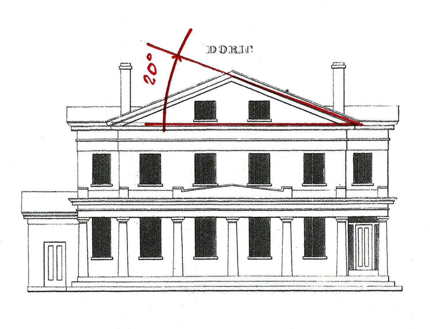
I have not explored the geometry of this door, nor the elevation below it.
These drawings with notes about the degree of roof pitch show how the Classical language of the Renaissance was no longer the standard as the Industrial Revolution began.
Pediments had a 4/12 roof pitch 22.5*. Now, as you can see, maybe not.
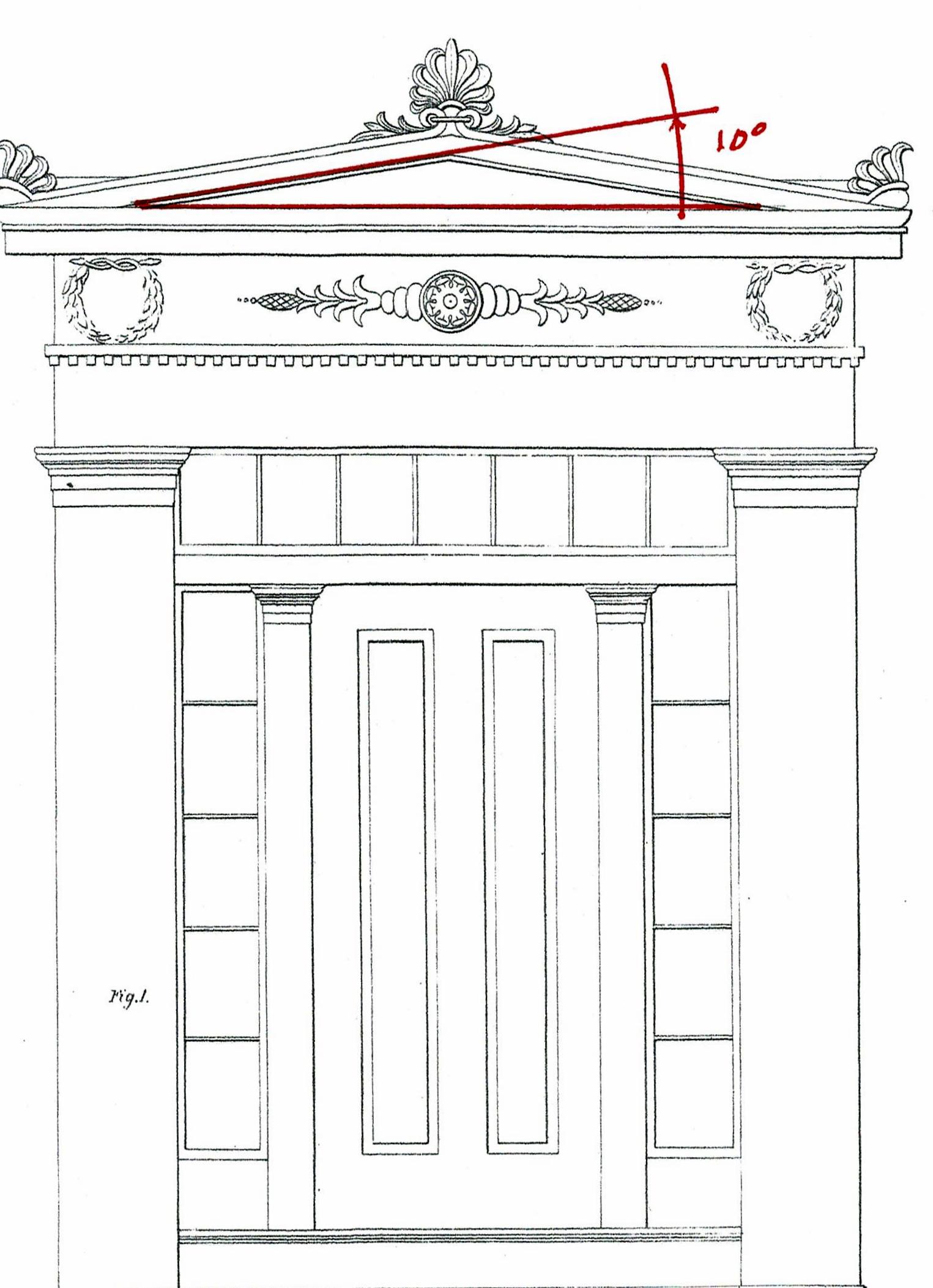
Perhaps the change in roof pitches was due to the availability of tin roofing sealed with lead. Before that 'roofing' was wood shingles which required at least a 4/12 (22.5*) pitch.
Slate roofing tiles were used in the UK, and in Europe. That technology was not here until the late 1840's.
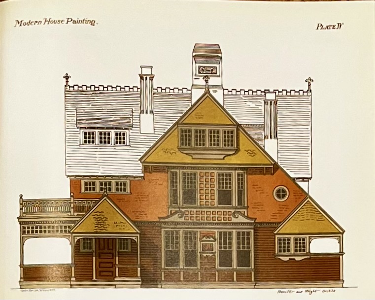
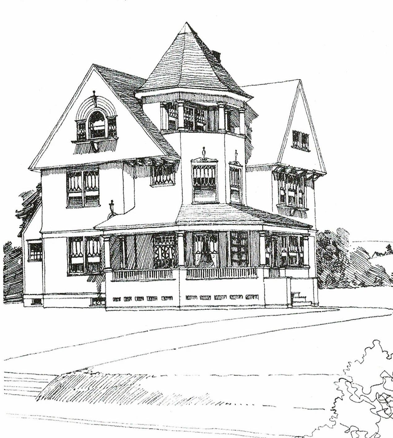
These 3 houses I chose for their variety and visual appeal. They represent the dramatic changes in design and construction from 1860 to 1900.
Carpenters who had trained under Master Builders before the Civil War now became 'architects': designers who knew construction intimately and worked closely with their contractors.
Colleges began to teach and graduate people who were architects. However their drafting tools were almost identical to those used in 1750 by Master Builders.
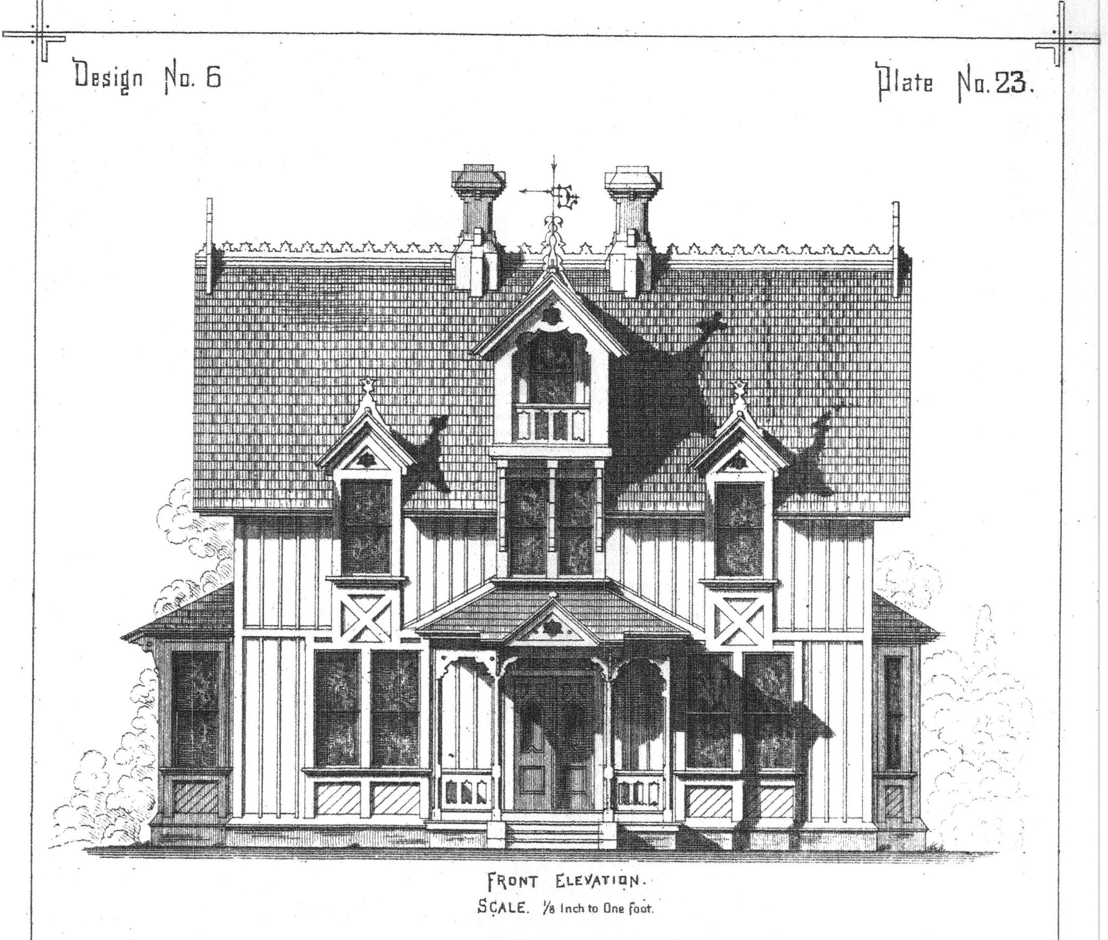
We were still using practical geometry, and we were still passing it on as much by learning from a master trades person, perhaps an architect, as by reading about it.
Looking at these images: While I can see their geometry, I have not studied it.
The first drawings is from Woodward, George E. and Thompson, Edward G, *A Victorian Housebuilder's Guide, Woodward's National Architect, NY, 1869.
The second is from Rossiter, E.K. and Wright, F.A. *Authentic Color Schemes for Victorian Houses, Comstock's Modern House Painting, 1883.
The third is from Shoppell, R.W. et al., Turn-of-the Century Houses, Cottages and Villas, NYC, c. 1900.
The * indicates a Dover Publications reprint.
The bibliography for the presentation is here:
https://www.jgrarchitect.com/2022/03/a-bibliography-for-my-traditional.html
![]()
Wednesday, March 30, 2022
A Bibliography for my Traditional Building Conference presentation, April 7, 2022.
Bibliography
Using the Historic Practice of Practical Geometry Today
- Berg, Donald J. American Country Building Design, Sterling Publishing Co, Inc. NY, 1997.
- Benjamin, Asher. The Country Builder’s Assistant, 1797, Dickman, printer, Greenfield, MA – reprint by Applewood Books, Bedford, MA. *The American Builder’s Companion, 6th edition, RP &C Williams, Boston, 1827.
- Biddle, Owen. *Young Carpenter’s Assistant, published by Benjamin Johnson, Philadelphia, 1807
- Charles, FWB, The Great Barn of Bredon, Its Fire and Reconstruction, Oxbow Monograph 76, 1997, Oxford Books, Oxford, UK.
- Downing, A. J. *The Architecture of Country Houses, originally published by D. Appleton & Company, 1850.
- Fletcher, Bannister, A History of Architecture on the Comparative Method, Charles Scribner’s Sons, NY, 17th Ed. 1967.
- Gibbs, James. *Book on Architecture, London, 1728
- Graham, Frank D., Audels Carpenter and Builders Guide, NY, 1923.
- Green, Bryan Clark. In Jefferson’s Shadow, the Architecture of Thomas R. Blackburn, Princeton University Press, NY, 2006
- Lafever. Minard, *The Modern Builder's Guide, NY, 1833.
- Langley, Batty, The Builder's Director, or Bench-Mate, London, 1751, reprint Westbrook Lithographers, Inc.,Westbury, NY.
- Nicholson, Peter. The Carpenter’s New Guide, 1793, London; 10th ed., Philadelphia, 1830.
- Pain, William, The Practical House Carpenter: or, Youth's Instructor, London, 1794, Gale Ecco reprint.
- Palladio, Andreas. *The 4 Books of Architecture, 1570, translated and published by Isaac Ware, London, 1738.
- Rossiter, E.K. and Wright, F.A. *Authentic Color Schemes for Victorian Houses, Comstock's Modern House Painting, 1883.
- Salmon, William, Palladio Londinensis, London, 1755, Gale Ecco reprint.
- Serlio, Sebastian. On Architecture, Lyon, France 1530, translated in 1611, available on-line. Translated by Vaughan Hart and Peter Hicks, 1996, Yale University Press, New Haven.
- Shaw, Edward. *The Modern Architect, Dayton & Wentworth, Boston, 1854.
- Shoppell, R.W. et al., Turn-of-the Century Houses, Cottages and Villas, NYC, c. 1900.
- Smith, Laurie, The Geometrical Design of St. David’s Cathedral Nave Ceiling, A Geometer’s Perspective, The Geometrical Design Works, 2017, printed Exeter, UK. The Geometric Design of Harmondsworth Great Barn, Historic Building Carpentry in partnership with The UK Carpenters Fellowship, 2021, printed Exeter, UK.
- da Vignola, Giancomo Barozzi, *Canon of the Five Orders of Architecture, translated by John Leeke, published by William Sherwin, 1669.
- Vitruvius, Marcus. *The Ten Books on Architecture, c. 10 BCE, translated by Morris Hick Morgan, Harvard University Press, 1914.
- Walker, George, and Tolpin, Jim, By Hound & Eye, Lost Art Press, Ft. Mitchell, KY, 2015. This book is a hands-on, first steps, introduction to using geometry in construction.
- Ware, William R, *The American Vignola, Norton and Co. NYC, 1903.
- Woodward, George E. and Thompson, Edward G, *A Victorian Housebuilder's Guide, Woodward's National Architect, NY, 1869.
![]()
Friday, February 25,2022
James Gibbs' steeples
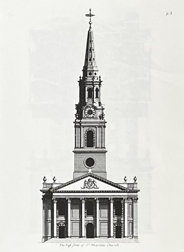
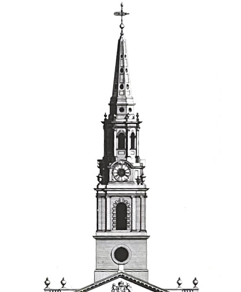
James Gibbs was the Surveyor of the Work for the design and construction of St. Martin in the Field, Trafalgar Square, London, begun in 1722, completed in 1726.
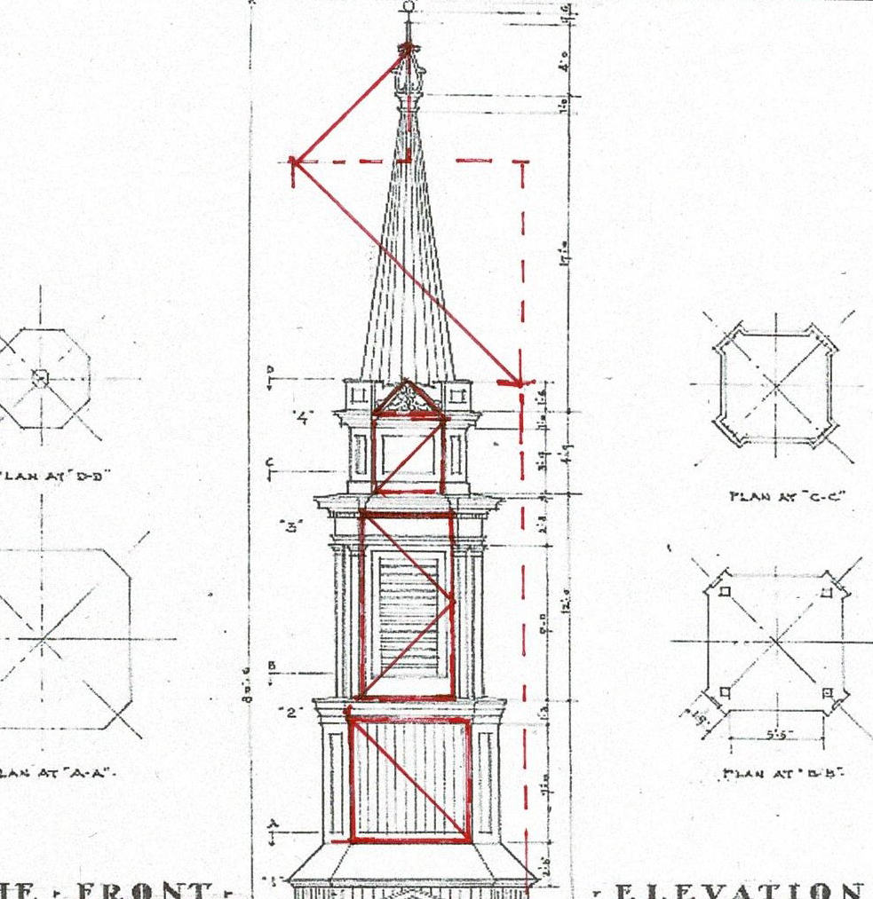
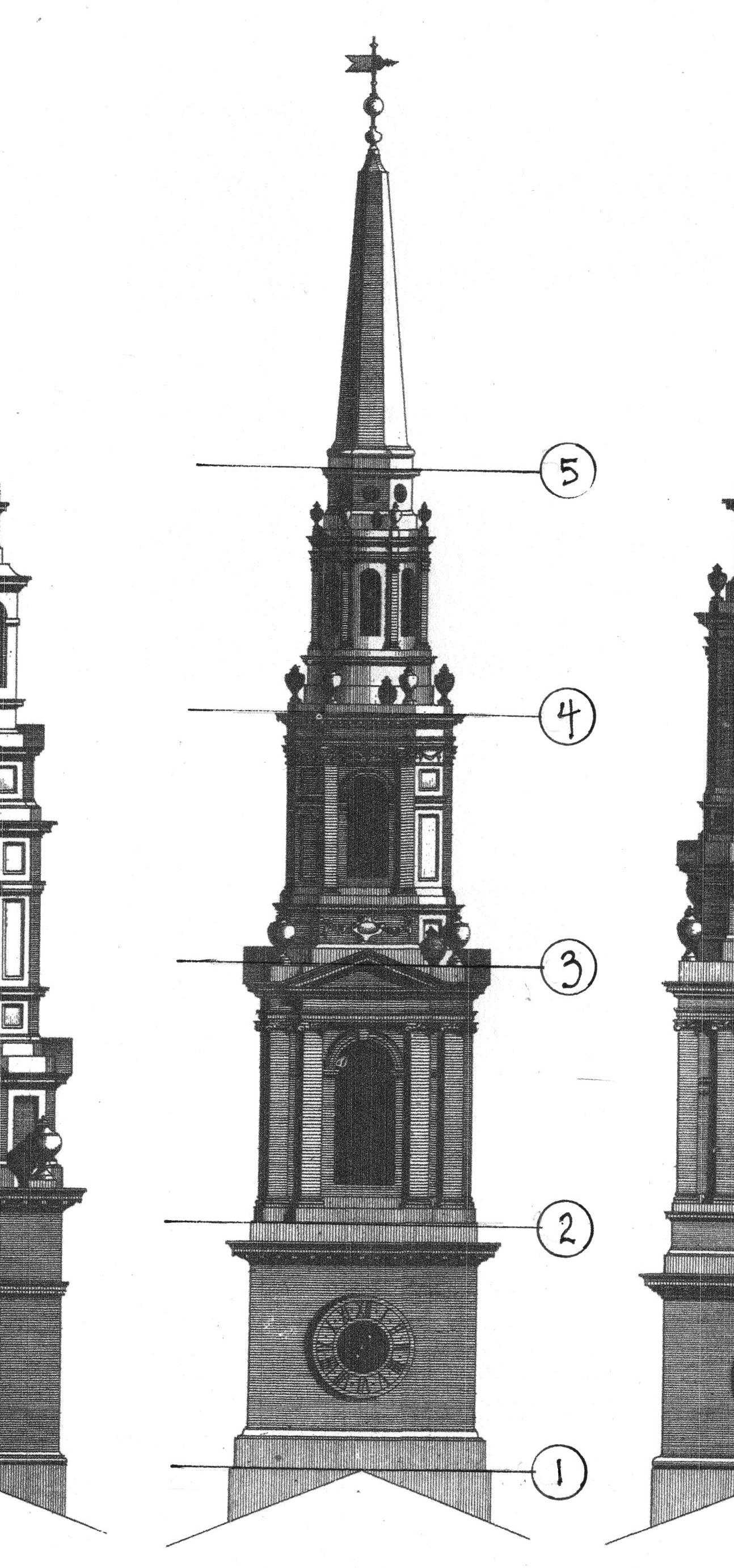
His pattern book, On Architecture, published in 1728, had 150 plates. 7 were engravings for St. Martin's. He writes that Plate II is "The Geometrical Plan of the Church and Portico, shewing the Disposition of the whole Fabrick." (Introduction - i) Plate III, shown here, is "The West Front and Steeple"
Many churches and steeples are included in Gibbs' book. Plates 29 and 30 show 6 images of steeples, all drawn for St. Martin's but not chosen. Plate 31 has 5 draughts of steeples for St. Mary le Strand.
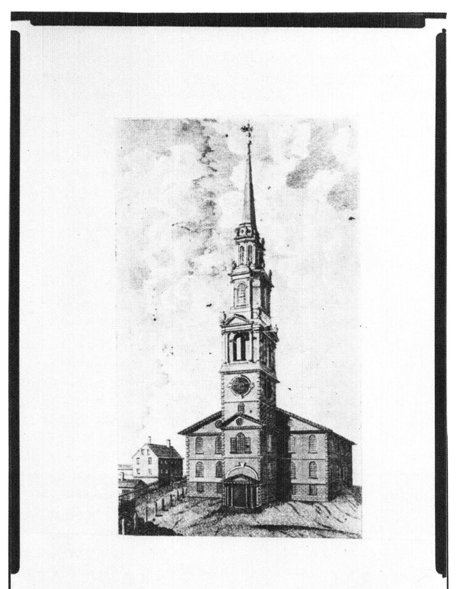
In 1775, the Providence (RI) Gazette, writing about the Baptist Meetinghouse, comments on the use of the "middle Figure in the 30th Plate of Gibbs designs" * for the church steeple.

This engraving is the draught (the architectural drawing) of the Geometric Plan of that steeple. Gibbs writes that while steeples are Gothick, "...they have their Beauties, when their parts are well dispos'd, and when the plans of the several Degrees and Orders of which they are compos'd gradually diminish and pass from one form to another without confusion, and when every Part has the appearance of a proper Bearing." (viii)
The Master Builder for the Baptist Meetinghouse was Joseph Brown. How did he know what to do from those instructions?
He was not only a builder but an astronomer, a scientist and a professor. He knew his Geometry.
How would the parts be 'well dispos'd' or well ordered. That could refers to the pattern of 'base, column and wall, architrave' for each section.
Or it might be how the parts are all the same height. I have marked on the engraving where each part begins and ends. Each provides physically and visually 'a proper Bearing' for the next level.
How did the parts 'gradually diminish'?
Below each steeple on Plates 29, 30 and 31 is a cartouche, a diagram: the plan for each steeple, showing the outlines of each steeple part.
This is the diagram for the middle steeple which was copied for the Baptist Meetinghouse.The image in the book is 1.5" square. It is the size of the image Joseph Brown, Master Builder, would have worked from.
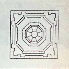
I have labeled the outlines of each part of the tower to correspond with my numbers on the steeple drawing above. (5) is the base of the 8 sided spire. The innermost circle is the cap where the weather vane is attached.
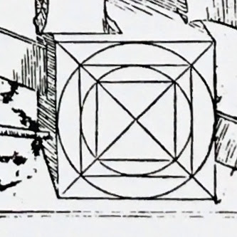
The parts layer one on the other following a diagram, a pattern - which I refer to as the square and its circle. This geometry was well known. It goes back in construction to at least the 7th c. in Constantinople. Serlio placed it on his frontispiece.**

This variation of the square and its circle, uses only the diagonals and adds the division of the square into quarters. As the design has 8 sided Parts (#3 and 4) and an octagonal spire, perhaps this diagram was used.

Where the Lines cross the square locates a smaller square, rotated. And those Lines locate the next. They determine the size and location of each Part of the steeple
The diagram is not meant to be a working drawing. Instead it directs the builder. It does not matter if it is not quite accurate. When the builder lays out the work he will adjust and refine the shapes to fit his frame.
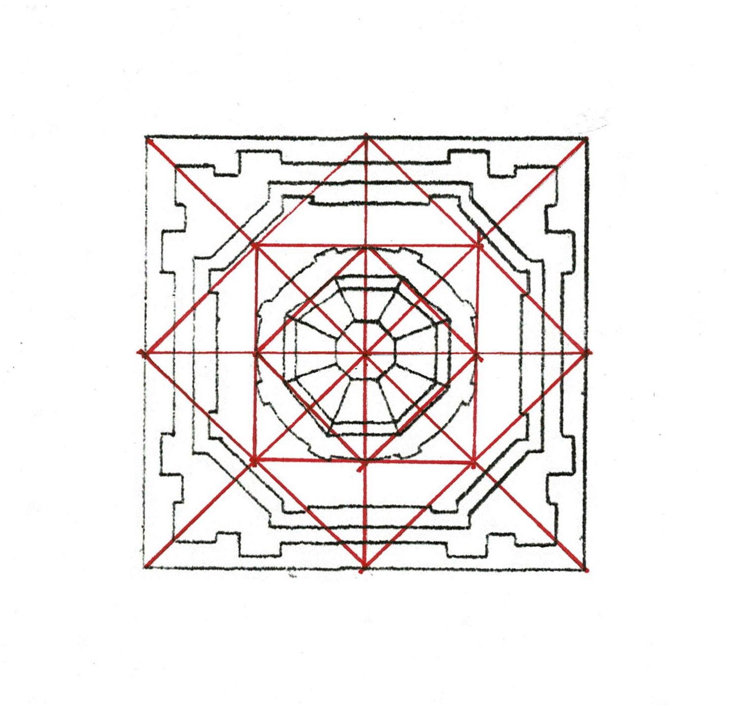
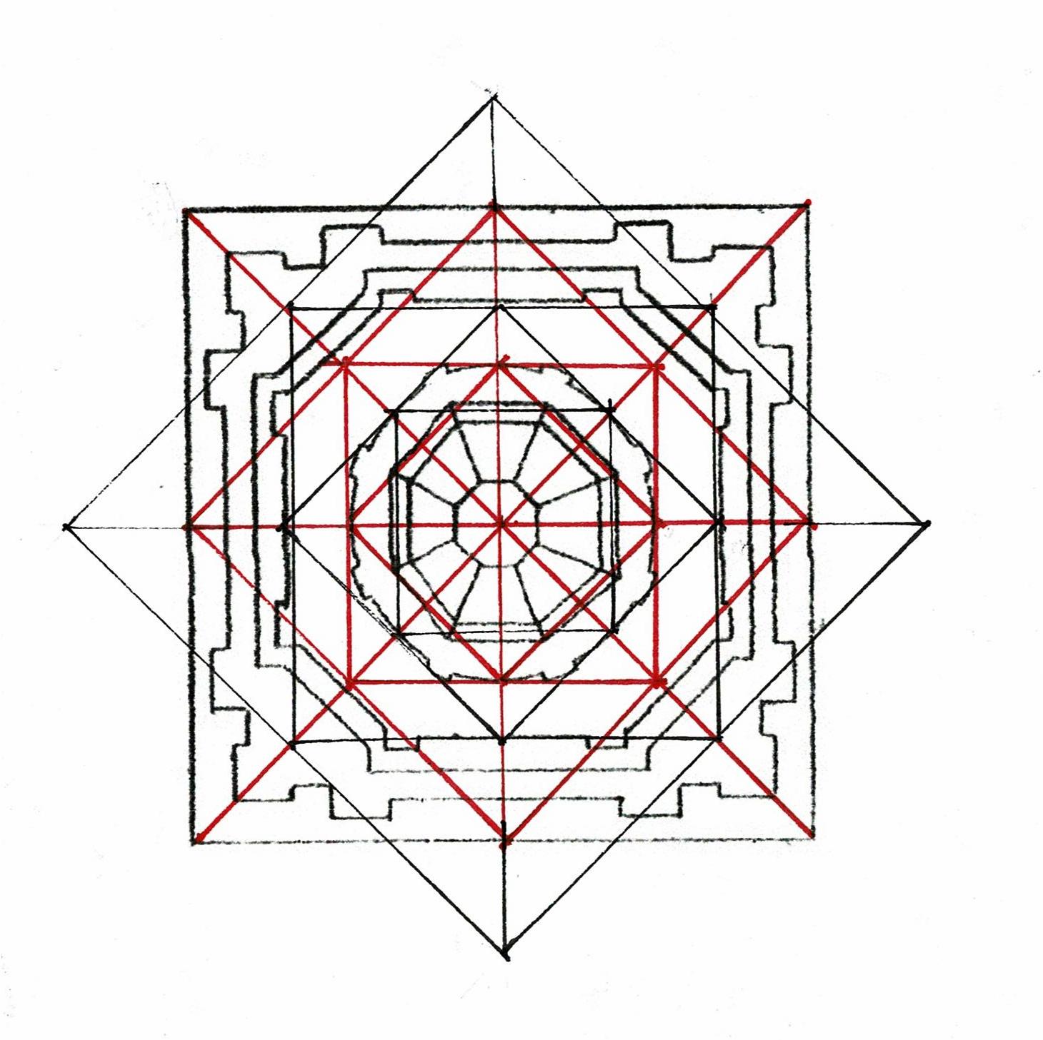
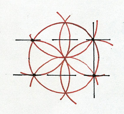
What happens when the first square is rotated - creating an 8 pointed star?

And the squares that fit inside that square are added? Drawn here in black over the first diagrams drawn in red.
The octagons of the Parts are laid out. Drawn on a framing floor the lengths for each wall would be easy to measure and set correctly.
It's done with just a length of twine and the knowledge of geometry.
The Providence, RI, Baptist Meetinghouse - with its steeple, drawn c. 1800. The image is now in the Library of Congress with the HABS drawings of the Meetinghouse.
* quote from American Architects and Their Books to 1848, ed: Hafertepe and O'Gorman, UMASS Press, 2001, Abbott Lowell Cummings' essay, The Availability of Architectural Books in Eighteenth-Century New England, p. 2.
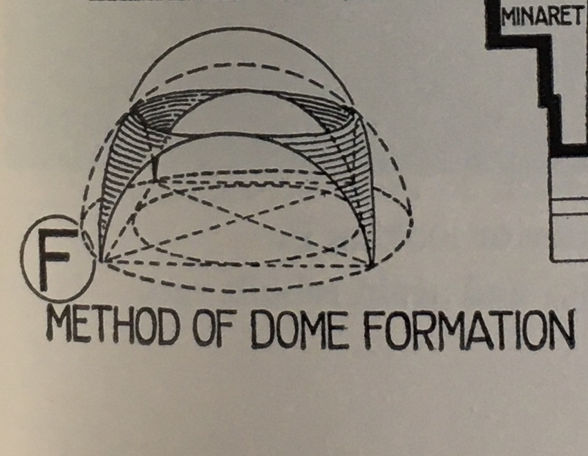
** the Geometry of Hagia Sophia's dome (Bannister Fletcher's diagram)
The lower right corner of Sebastiano Serlio's frontispiece of his On Architecture: a cube with its diagonals, the circle and the next square that fits within that circle. As can be seen in the steeples drawn by James Gibbs, these circles and squares can grow in and/or out.
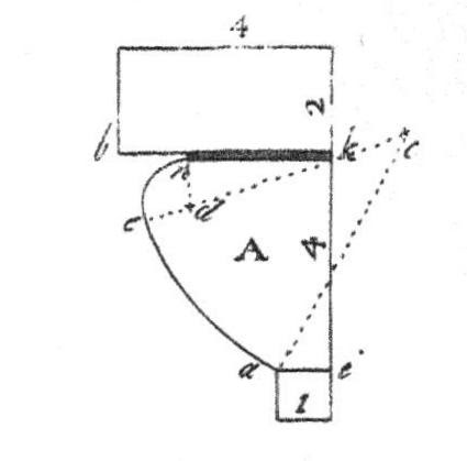
Connect 2 points (solid black line). This will be the length (front to back) of the central form. Add the Lines ( dashed black lines ) perpendicular to the first Line.
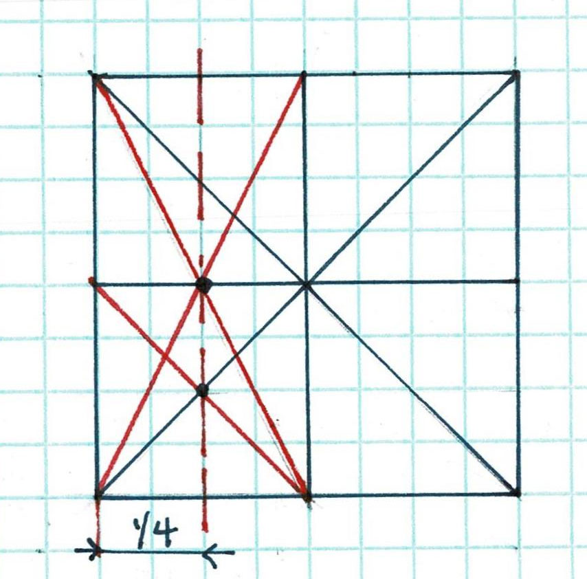
If the central form were to be a square, where the dashed lines cross the daisy petals mark 2 more points. The dashed, black vertical line is the 4th side of the square: each side is the length of the radius.
This central form is not that wide. James Gibbs choose to use the 2 vertical points of the daisy wheel to locate the Line for the left side of the porch and the caretaker's quarters. The black box is that rectangle.
The rest of the layout is based on the interior space. Gibbs assumes the workmen who might copy his 'draught' know how to build walls; he is not providing a construction document.
The wall between the porch and the living quarters is set beside the center of the rectangle. This makes the porch a little more gracious. It is also the way a mason sets lines today, building beside his lines.
To determine the location of the wings to the main body of the menagery Gibbs divides the rectangle into 8 parts.
Here is the diagram showing how to use Lines to divide a rectangle into 8 equal sections.
I call this 'The rule of Thirds' because artists use this diagram as a design tool and that;s what they call it. It's the 3x3 pattern that appears when we edit cellphone pictures. That pattern is 1/3. Here the division is into 1/2, 1/4, and 1/8. **
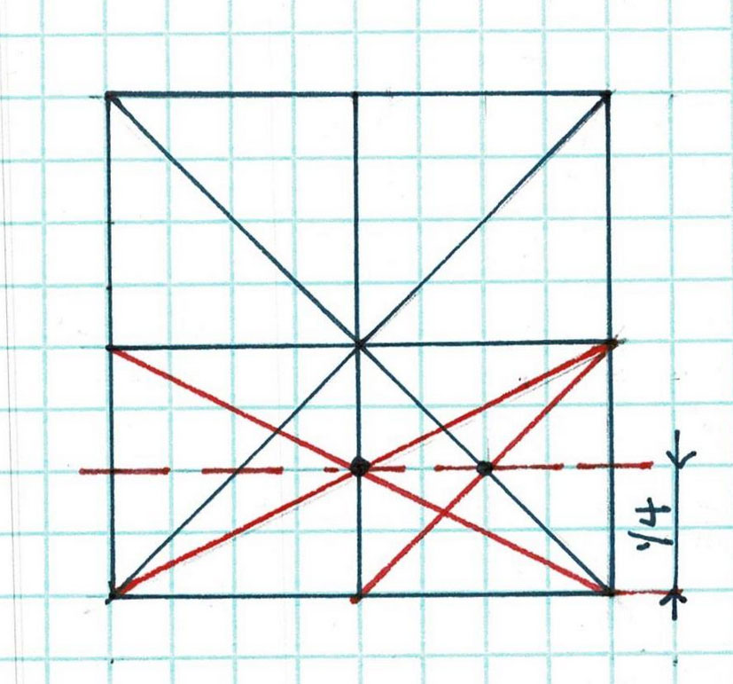
The wings of the menagery are set back 1/8 the depth of the main block in the front and the back. I've drawn the open porch divided into 4 equal parts and extended the Lines to show the depth of the wings' setback. This offset is used on both wings, front and back.
The wings are themselves both 3/4/5 rectangles. They are square: a 3/4/5 triangle always has a 90* corner. The diagram shows how to layout a 'right triangle' using Lines.
The 3/4/5 rectangIe was a common way to add a wing to an existing building. If the mason set his length against the central form at 4 units and his width at 3 units, his wing would be square against the main block. His stone work would be true. I have drawn the 3 x 4 units here. I have also left my pencil marks for further information (enlarge the drawing!)
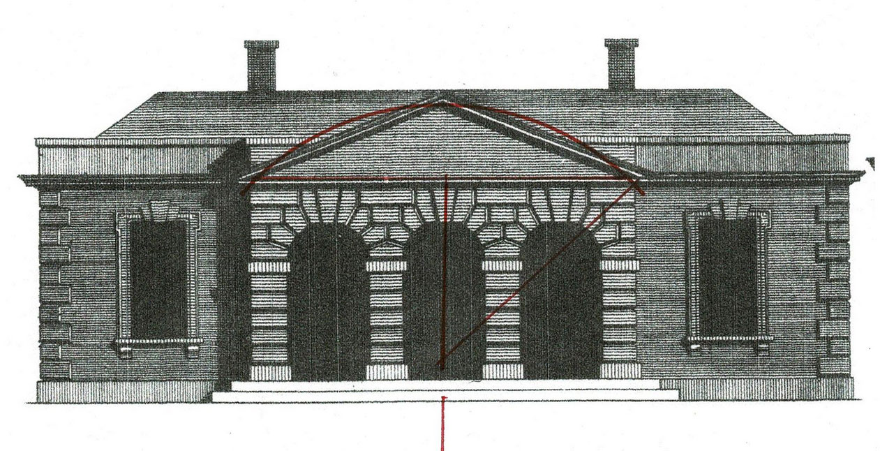
The layout for the 3 arched openings on the pavilion's porch also uses the Rule of Thirds.
Here is the diagram above turned 90*. Note where the red lines cross the
black lines above my red dashed line. Those points divide the square into thirds. Drop a vertical there (see red lines above) to mark the columns' center line.
While this menagery design is more complex to write about than Gibbs' other design*, it is quite easy to lay out with a compass and straight edge. A trained workman would have known the steps, some of which, for example the 3/4/5 rectangle, are used today.
The elevation?It's4 squares and the same pediment layout that Gibbs used on the menagery design which was built.
Gibbs began the elevation from the same inside dimensions he used for the floor plan.
A note: the windows are centered on the rooms' inside wall, but not on the exterior width of the wing. The quions are such a strong visual vertical that they appear as an anchor. The windows were centered on the rest of the wall.
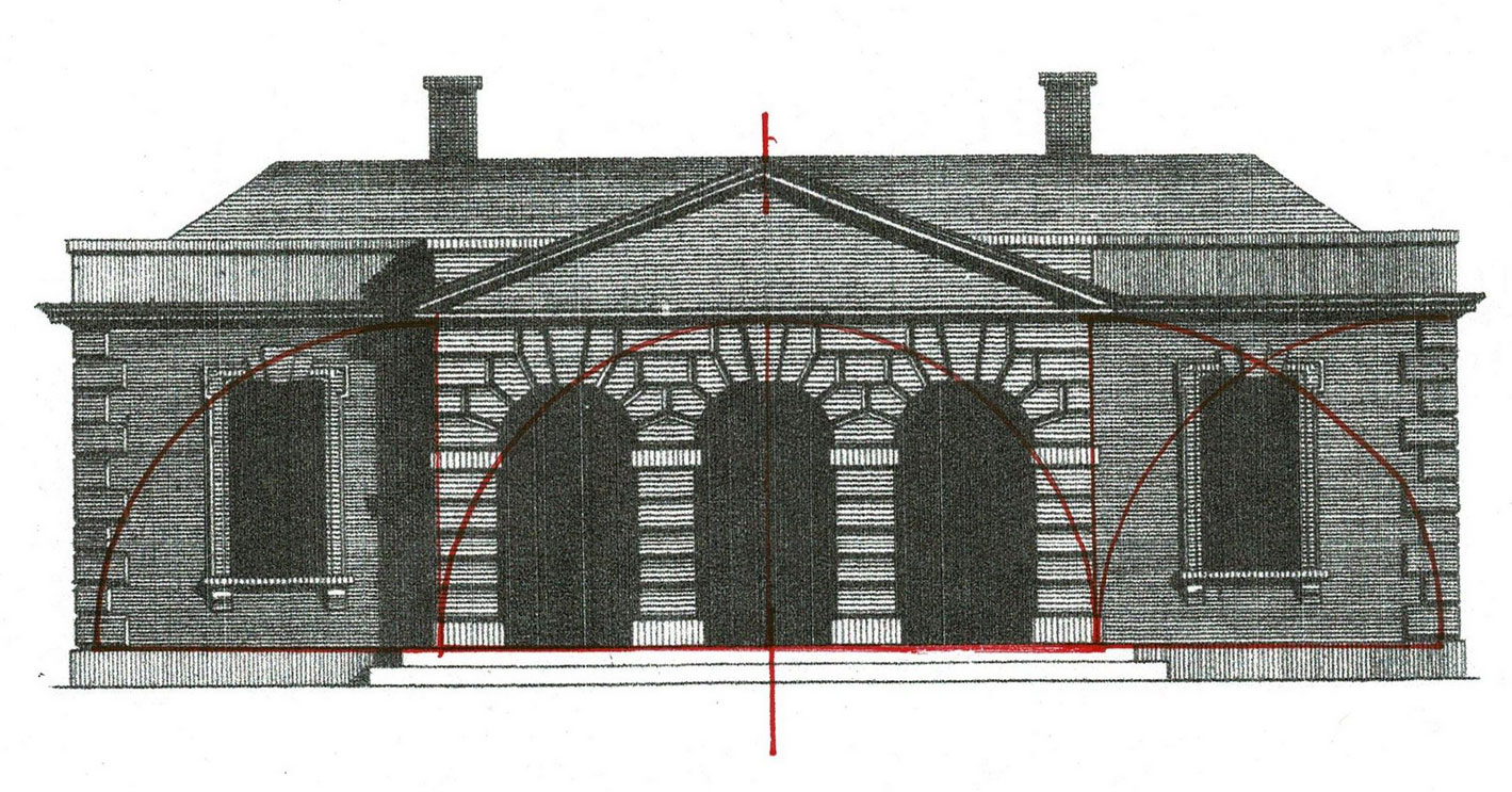
The pediment is drawn following the rules described by Serlio. For step by step instructions, refer to Part 1 of 2 of this post of the draughts for the Menagery.*
* Gibbs' book On Architecture, published in 1728, includes 150 plates: plans, elevations, sections and perspectives of buildings Gibbs had designed and built. The quote is from his introduction, page i. A reprint is available from Dover Publications.
** I've posted about The Rule of Thirds in more detail here:
https://www.jgrarchitect.com/2020/08/lesson-6-rule-of-thirds-part-1_21.html
https://www.jgrarchitect.com/2020/08/lesson-6-rule-of-thirds-part-2-serlio.html
Tuesday, November 29, 2022
Virginia Folk Housing, Part 2 of an update
Tuesday, November 14, 2022
Virginia Folk Housing, Part 1 an update
Wednesday, October 5, 2022
Serlio's Lines
Monday, September 26, 2022
The Geometry of Ionic volutes
Wednesday, July 27, 2022
The Baptist Church of Streetsboro, Ohio, Part 1
Wednesday, July 26, 2022
The Baptist Church of Streetsboro, Ohio, Part 2
Sunday, June 19, 2022
James Gibbs' Of Architecture, Draughts for a Menagery, Part 2 of 2
Thursday, April 21, 2022
The Parson Capen House, 1683, Topsfield, MA
Tuesday, April 19, 2022
The geometrical design of Harmondsworth Great Barn, Laurie Smith
Friday, April 1, 2022
Images from my talk on the Historic Practice of Practical Geometry , April 7, 2022
Wednesday, March 30, 2022
A Bibliography for my Traditional Building Conference presentation, April 7, 2022.
Friday, February 25,2022
James Gibbs' steeples
>>>>